Sensor-based road bridge state monitoring method and system

A state monitoring system and sensor technology, applied in the direction of instruments, measuring devices, etc., can solve the problems of low monitoring efficiency and high monitoring cost, and achieve the effect of low monitoring cost, high monitoring efficiency and comprehensiveness

Active Publication Date: 2017-11-24
SHENZHEN SHENGLU IOT COMM TECH CO LTD
View PDF6 Cites 6 Cited by
  • Summary
  • Abstract
  • Description
  • Claims
  • Application Information

AI Technical Summary

Problems solved by technology

[0006] In view of this, the embodiments of the present invention provide a sensor-based road and bridge condition monitoring method and system to solve the problems of high monitoring cost and low monitoring efficiency existing in existing road and bridge condition monitoring technologies

Method used


Image

  • Sensor-based road bridge state monitoring method and system
  • Sensor-based road bridge state monitoring method and system
  • Sensor-based road bridge state monitoring method and system

Examples


Embodiment 1

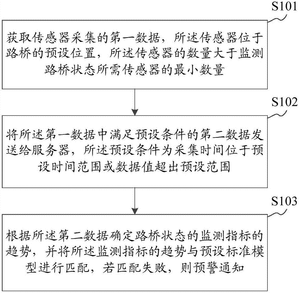
[0046] figure 1 A flow chart of a sensor-based road and bridge state monitoring method provided by Embodiment 1 of the present invention is shown. Such as figure 1 As shown, the sensor-based road and bridge state monitoring method specifically includes the following steps S101 to S103.

[0047] Step S101: Obtain first data collected by sensors, the sensors are located at preset positions of the road bridge, and the number of the sensors is greater than the minimum number of sensors required to monitor the state of the road bridge.

[0048] Wherein, the preset position is set according to the monitoring needs, and the sensors in the preset position monitor each monitoring index of the state of the road and bridge, and collect the first data in real time, and the first data includes the data of the corresponding monitoring index (such as pressure value, temperature and humidity value), the type of sensor, and the location information of the sensor. The location information can b...

Embodiment 2

[0058] On the basis of Embodiment 1, preferably, the sensors include multiple types, and each of the sensors corresponds to one of the monitoring indicators for monitoring the state of the road and bridge; the number of the sensors is to monitor the road and bridge Multiples of the sum of the minimum quantities of each sensor required for each monitoring index of the state.

[0059] For example, a variety of sensors include: temperature sensors, humidity sensors, slope sensors, displacement sensors, pressure sensors, and crack sensors. These sensors respectively monitor temperature monitoring indicators, humidity monitoring indicators, slope monitoring indicators, displacement monitoring indicators, pressure monitoring indicators and crack monitoring indicators in the monitoring indicators, making the monitoring of road and bridge status more comprehensive. At the same time, the one-to-one monitoring relationship of a sensor corresponding to one of the monitoring indicators fo...

Embodiment 3

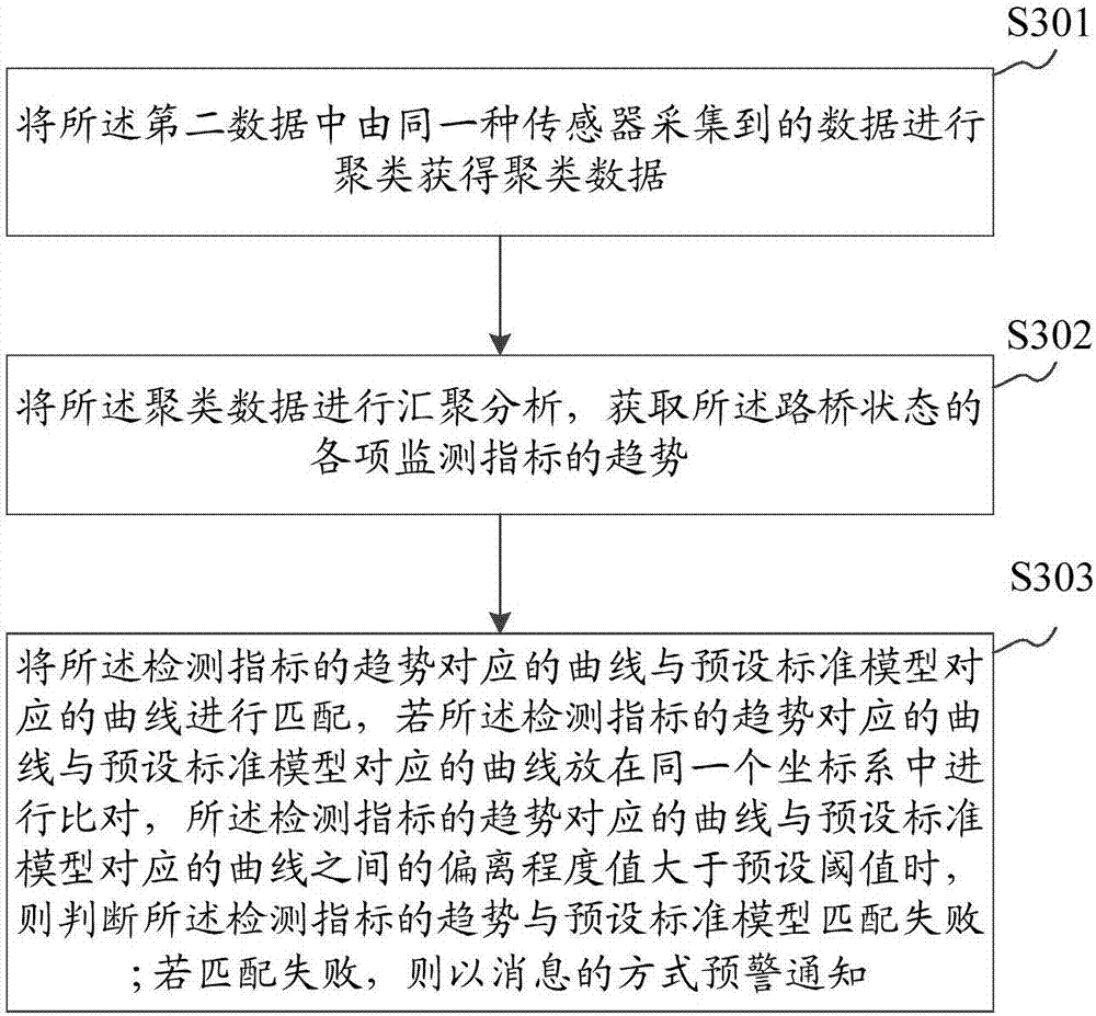
[0061] On the basis of embodiment two, as embodiment three of the present invention, image 3 A specific implementation flow chart of step S103 of the sensor-based road and bridge state monitoring method provided by Embodiment 1 of the present invention is shown. Step S103 specifically includes the following steps S301, S302 and S303.

[0062] Step S301: cluster the data collected by the same sensor in the second data to obtain clustered data.

[0063] It can be known from step S101 that the first data includes data of corresponding monitoring indicators (such as pressure value, temperature and humidity value), type of sensor, and location information of the sensor. Apparently, the second data also includes data of corresponding monitoring indicators (such as pressure value, temperature and humidity value), type of sensor, and location information of the sensor. It can be known from the description in Embodiment 3 that each of the sensors corresponds to one of the various mo...


PUM


Abstract

The invention relates to the technical field of data monitoring, and provides a sensor-based road bridge state monitoring method and system. The method comprises the steps that the first data acquired by sensors are acquired, the sensors are arranged at the preset positions of the road bridge, and the number of the sensors is greater than the minimum number of the sensors required for monitoring the road bridge state; the second data meeting the preset condition in the first data are transmitted to a server, wherein the preset condition is that the acquisition time is within the preset time range or the data value exceeds the preset range; and the trend of the monitoring indexes of the road bridge state is determined according to the second data and the trend of the monitoring indexes is matched with a preset standard model, and a warning notice is given if matching fails. The comprehensiveness of the monitoring result can be guaranteed by the sensors arranged at the preset positions of the road bridge, and monitoring of the road bridge state is not influenced by the work state of certain sensors so that secondary construction and the monitoring cost and the low efficiency caused by secondary construction can be avoided, the monitoring cost is low and the monitoring efficiency is high.

Description

technical field [0001] The invention belongs to the technical field of data monitoring, and in particular relates to a sensor-based road and bridge state monitoring method and system. Background technique [0002] At present, the condition monitoring of long-span road bridges to ensure the safety of road bridge structures and achieve early pre-conditioning, avoiding the development of structural damage or degradation, reducing expensive repair costs and even structural collapse has become a hot issue in today's engineering circles. Therefore, the condition monitoring technology of span road bridge has become an important field of research and development of road and bridge engineering. [0003] There are two main methods for road and bridge condition monitoring: [0004] One is: laboratory analysis based on manually collected raw data. The realization of this technical solution requires a lot of manpower and material resources, and the efficiency and accuracy of analysis a...

Claims


Application Information

Patent Timeline
Patent Type & Authority Applications(China)
IPC IPC(8): G01D21/02
CPCG01D21/02
Inventor 杜光东
Owner SHENZHEN SHENGLU IOT COMM TECH CO LTD
Why Eureka
Try Eureka