
Aeroengine Rotor Vibration Test System

A technology of aero-engine and rotor vibration, which is applied in the testing of machine gears/transmission mechanisms, etc., can solve the problem of inability to monitor the fundamental frequency component value of the rotor in real time, and achieve the effects of high accuracy, improved data analysis efficiency, and high data analysis efficiency.

Active Publication Date: 2019-09-20
AECC HUNAN AVIATION POWERPLANT RES INST
View PDF8 Cites 0 Cited by
  • Summary
  • Abstract
  • Description
  • Claims
  • Application Information

AI Technical Summary

Problems solved by technology

[0008] The invention provides an aero-engine rotor vibration test system to solve the technical problem that the existing aero-engine vibration test system cannot monitor the value of the fundamental frequency component of the rotor in real time

Method used


Image

  • Aeroengine Rotor Vibration Test System
  • Aeroengine Rotor Vibration Test System
  • Aeroengine Rotor Vibration Test System

Examples


Embodiment Construction

[0043] It should be noted that, in the case of no conflict, the embodiments in the present application and the features in the embodiments can be combined with each other. The present invention will be described in detail below with reference to the accompanying drawings and examples.

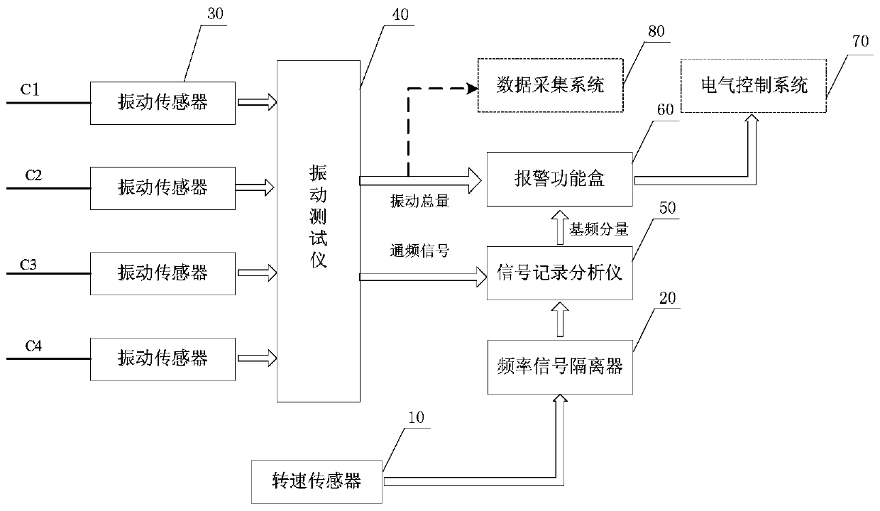
[0044] refer to image 3, the preferred embodiment of the present invention provides a kind of aeroengine rotor vibration test system, comprises speed sensor 10, frequency signal isolator 20, vibration sensor 30, vibration tester 40 and signal recording analyzer 50, wherein, speed sensor 10, Used to measure the rotational speed signal of the rotor of the aero-engine; the frequency signal isolator 20 is connected to the rotational speed sensor 10, and is used to shape the rotational speed signal measured by the rotational speed sensor 10, and output an isolated rotational speed signal; the vibration sensor 30 is used to feel the rotational speed of the aero-engine The vibration charge signal of...


PUM


Abstract

The invention discloses an aeroengine rotor vibration test system comprising a rotating speed sensor, a frequency signal isolator, a vibration sensor, a vibration tester and a signal record analyzer. The rotating speed sensor is used for measuring the rotating speed signal of an aeroengine rotor. The frequency signal isolator is used for shaping the rotating speed signal measured by the rotating speed sensor and outputting the isolated rotating speed signal. The vibration sensor is used for sensing the vibration charge signal of each vibration measuring point of the aeroengine. The vibration tester is used for converting the vibration charge signal sensed by the vibration sensor into a vibration voltage signal. The signal record analyzer is used for synchronously acquiring the rotating speed signal and the vibration voltage signal and extracting the rotor vibration fundamental frequency component of the vibration voltage signal and displaying the curve of the vibration amplitude of the rotor vibration fundamental frequency component changing along with the rotating speed and / or the time. The aeroengine rotor vibration test system is high in data analysis efficiency and high in the measured fundamental frequency component value accuracy.

Description

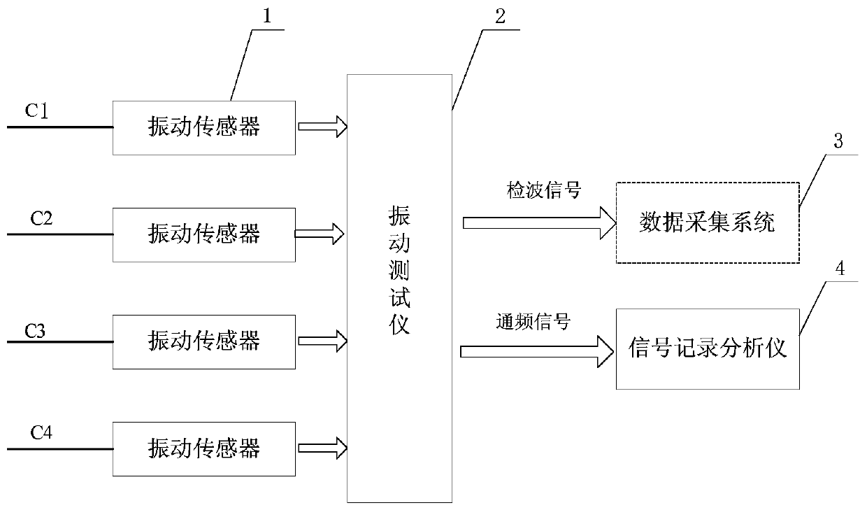
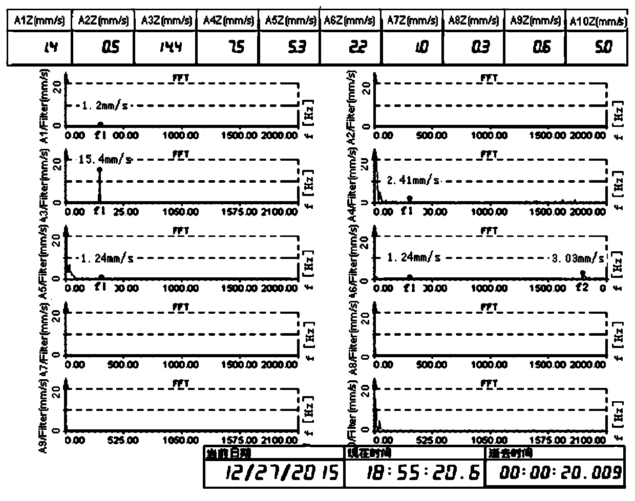
technical field [0001] The invention relates to the field of aero-engine rotor testing, in particular to an aero-engine rotor vibration testing system. Background technique [0002] Vibration testing is an important link in the development and testing of aero-engines. The existing aero-engine rotor vibration testing system adopts the test method of monitoring the total vibration and real-time FFT (Fast Fourier Transformation, Fast Fourier Transformation) spectrum within the specified frequency band. Analysis is the main method. When the total amount of vibration exceeds the limit, an alarm will be issued manually. The operator will stop after seeing the alarm indicator light on. The change of the fundamental frequency component of the rotor vibration needs to be analyzed afterwards, and the change curve needs to be passed through other software or Excel afterwards. Draw it out. [0003] Such as figure 1 as shown, figure 1 It is the functional block diagram of the existing...

Claims


Application Information

Patent Timeline
Patent Type & Authority Patents(China)
IPC IPC(8): G01M13/02
Inventor 吴建芳刘金南吴伟力徐斌赵黎李胜斌
Owner AECC HUNAN AVIATION POWERPLANT RES INST
Learn More