Dispersion test equipment suitable for low-permeability soil

A test equipment and low-permeability technology, applied in the field of environmental geotechnical engineering, can solve the problems of easy fracture of soil columns, high labor costs, and small water output, and achieve the effects of avoiding sidewall penetration, shortening test time, and maintaining stability.

Inactive Publication Date: 2017-11-24
SHANGHAI GEOTECHN INVESTIGATIONS & DESIGN INST
View PDF6 Cites 7 Cited by
  • Summary
  • Abstract
  • Description
  • Claims
  • Application Information

AI Technical Summary

Problems solved by technology

At present, the research on hydrodynamic dispersion parameters is mainly realized through the tracer model and the one-dimensional sand column test, that is, after filling the soil column, the tracer is sent to the water tank or Martens bottle to manually read the conductivity and indirectly measure the concentration. , the test porous medium is mainly coarse sand, pebbles, etc., and the soil column is filled with dried remolded soil, which has a large gap with the original soil
[0003] For soils with small particles and low permeability coefficient (such as sandy silt and silt), if the soil column method is used, it will take a long time to fill the remolded soil and the labor cost will be high; There are phenomena such as the soil column is easy to break and the water output is small, which has caused more inconvenience to the normal conduct of the experiment.
In addition, most of the current indoor dispersion tests are to take water samples at regular intervals and use a portable conductivity meter to measure the conductivity. Obtain the change value of conductivity in the whole test, and waste a lot of manpower and material resources at the same time

Method used


Image

  • Dispersion test equipment suitable for low-permeability soil
  • Dispersion test equipment suitable for low-permeability soil
  • Dispersion test equipment suitable for low-permeability soil

Examples


Embodiment

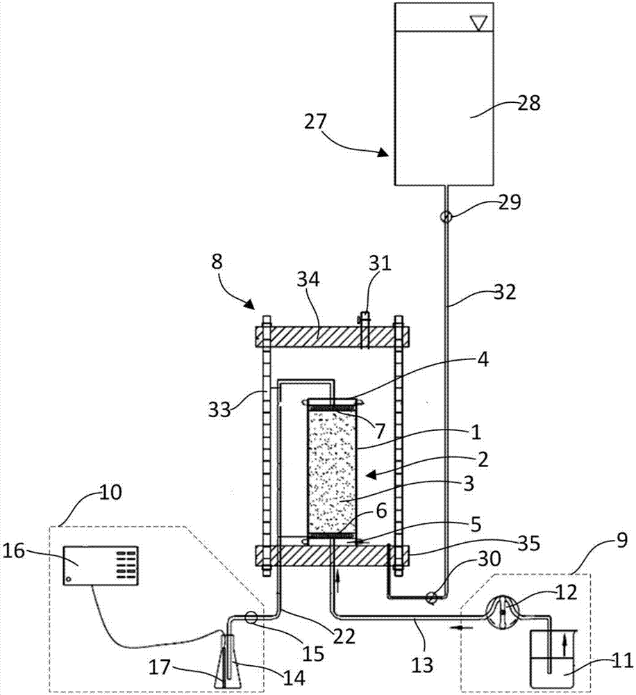
[0019] Example: such as figure 1 As shown, the present embodiment specifically relates to a dispersion test device suitable for low-permeability soil, the dispersion test device includes a hydraulic chamber 8 and a permeameter chamber 2 for containing the test soil column 3; The pressure component 27 is connected; the osmometer chamber 2 is arranged inside the water pressure chamber 8; the osmometer chamber 2 includes the instrument chamber top plate 4, the instrument cavity bottom plate 5 and the cylindrical flexible side wall 1, the instrument cavity top plate 4 and the instrument cavity The chassis 5 forms a sealed connection with both ends of the flexible side wall 1 respectively; the chassis 5 of the instrument cavity is connected with a tracer injection component 9 , and the top plate 4 of the instrument cavity is connected with a tracer collection and detection component 10 .

[0020] Such as figure 1 As shown, in this embodiment, the flexible side wall 1 is made of a ...


PUM


Abstract

The invention discloses dispersion test equipment suitable for low-permeability soil. The dispersion test equipment comprises a water pressure chamber and a permeameter chamber for accommodating a testing earth-pillar; the water pressure chamber communicates with a pressurizing chamber; the permeameter chamber is arranged in the water pressure chamber and comprises a top disc of the permeameter chamber, a bottom disc of the permeameter chamber and a cylindrical flexible side wall, wherein the top disc of the permeameter chamber and the bottom disc of the permeameter chamber are hermetically connected to two ends of the flexible side wall, separately; and the bottom disc of the permeameter chamber is connected to a tracer agent injection assembly, and the top disc of the permeameter chamber is connected to a tracer agent collecting and detecting assembly. The dispersion test equipment disclosed by the invention has the advantages that under the water pressure action of the water pressure chamber, the testing earth-pillar is tightly wrapped by the flexible side wall, so that side wall permeation caused by a gap between the testing earth-pillar and the flexible side wall is avoided; meanwhile, the testing earth-pillar is kept in a tight state by means of the water pressure, and is unlikely to break.

Description

technical field [0001] The invention belongs to the field of environmental geotechnical engineering, and in particular relates to a dispersion test device suitable for low-permeability soil. Background technique [0002] Dispersion parameter is one of the most important parameters for studying the migration and transformation of pollutants in soil and groundwater. The most reliable way to measure the dispersion is to conduct a dispersion test. At present, the research on hydrodynamic dispersion parameters is mainly realized through the tracer model and the one-dimensional sand column test, that is, after filling the soil column, the tracer is sent to the water tank or Martens bottle to manually read the conductivity and indirectly measure the concentration. , the test porous medium is mainly coarse sand, pebbles, etc., and the soil column is filled with dried remolded soil, which has a large gap with the original soil. [0003] For soils with small particles and low permeab...

Claims


Application Information

Patent Timeline
Patent Type & Authority Applications(China)
IPC IPC(8): G01N15/08
CPCG01N15/082G01N2015/0034
Inventor 许丽萍李韬王蓉沈超张亚娇陈展李梅宋晓光
Owner SHANGHAI GEOTECHN INVESTIGATIONS & DESIGN INST
Why Eureka
Try Eureka