Eureka AIR delivers breakthrough ideas for toughest innovation challenges, trusted by R&D personnel around the world.

Detection device for LED light bar

A technology for LED strips and testing equipment, which is used in lamp testing, optical testing for flaws/defects, etc., and can solve problems such as low efficiency and excessive labor.

Pending Publication Date: 2017-11-24
台龙电子(昆山)有限公司
View PDF6 Cites 5 Cited by
  • Summary
  • Abstract
  • Description
  • Claims
  • Application Information

AI Technical Summary

Problems solved by technology

LED electrical performance tester, including the CPU control unit, signal source circuit, measurement circuit, input and output distribution circuit and test interface, which are connected to each other in sequence. In the market, the LED light strip is usually brought to two instrument positions for testing separately, and the efficiency is high. Low, labor-intensive; the market has not yet solved such problems

Method used


Image

  • Detection device for LED light bar
  • Detection device for LED light bar

Examples


Embodiment Construction

[0017] The present invention will be specifically introduced below in conjunction with the accompanying drawings and specific embodiments.

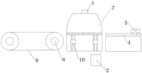
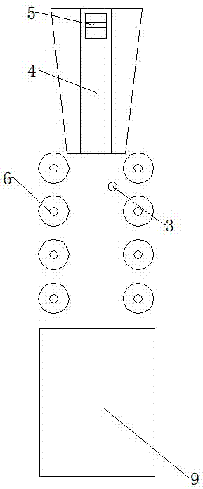
[0018] LED light strip testing equipment, including: a suction moving assembly that sucks up the LED light strip and transmits it to the detection entrance, an optical detector 1 that detects the LED light strip, and a delivery roller 6 that is set at the lower end of the optical detector 1 and limits the LED light strip Components, the electrical tester 2 located at the lower end of the limit transmission component, the electrical probe 3 connected to the electrical tester 2 and in contact with the LED light bar, and the conveyor belt 9 assembly that receives the tested LED light bar. It should be noted that the optical detector 1 used in the present invention is not limited, and the general optical detector 1 can be used. As an embodiment, the optical detector 1 can be selected from Beijing Quanou Optical Detector Co., Ltd. Universal de...


PUM


Abstract

The invention discloses a detection device for an LED (Light Emitting Diode) light bar. The detection device comprises an absorbing moving component, an optical detector, a conveying roller component, an electric detector, an electric probe and a conveying belt component, wherein the absorbing moving component is used for absorbing the LED light bar and conveying to a detection inlet; the optical detector is used for detecting the LED light bar; the conveying roller component is arranged at the lower end of the optical detector and is used for limiting the LED light bar; the electric detector is arranged at the lower end of a limiting conveying component; the electric probe is connected with the electric detector and is in contact with the LED light bar; the conveying belt component is used for receiving the detected LED light bar. The detection device for the LED light bar provided by the invention is capable of simultaneously completing optical detection and electric detection, the whole process is automatic, the detection efficiency is increased and the manpower is reduced.

Description

technical field [0001] The invention relates to the production field of an LED light bar, in particular to a detection device for an LED light bar. Background technique [0002] With the widespread use of LED light strips, the market's quality requirements for LED light strips are gradually increasing. It is necessary to test the optical and electrical properties of LED light strips before they can be shipped. Common defects encountered by the device are detected. LED electrical performance tester, including the CPU control unit, signal source circuit, measurement circuit, input and output distribution circuit and test interface, which are connected to each other in sequence. In the market, the LED light strip is usually brought to two instrument positions for testing separately, and the efficiency is high. Low and labor-intensive; the market has not yet solved such problems. Contents of the invention [0003] In order to solve the deficiencies of the prior art, the obje...

Claims


Application Information

Patent Timeline
IPC IPC(8): G01N21/95G01R31/44
CPCG01N21/95G01R31/44
Inventor 李妙玲
Owner 台龙电子(昆山)有限公司
Why Eureka
Eureka Blog
Learn More