Device for changing optical pulse waveform

A technology of optical pulse and waveform, which is applied in optics, optical components, instruments, etc., can solve the problems of inconvenience, multiple parts replacement, single optical pulse waveform, etc., and achieve the effect of convenient use and convenient maintenance

Active Publication Date: 2017-11-24
WUHAN CHINA STAR OPTOELECTRONICS TECH CO LTD
View PDF6 Cites 0 Cited by
  • Summary
  • Abstract
  • Description
  • Claims
  • Application Information

AI Technical Summary

Problems solved by technology

[0004] The invention provides a device for changing the optical pulse waveform, which is used to solve the technical problems in th

Method used


Image

  • Device for changing optical pulse waveform
  • Device for changing optical pulse waveform
  • Device for changing optical pulse waveform

Examples


Embodiment Construction

[0031] The present invention will be further described below in conjunction with accompanying drawing.

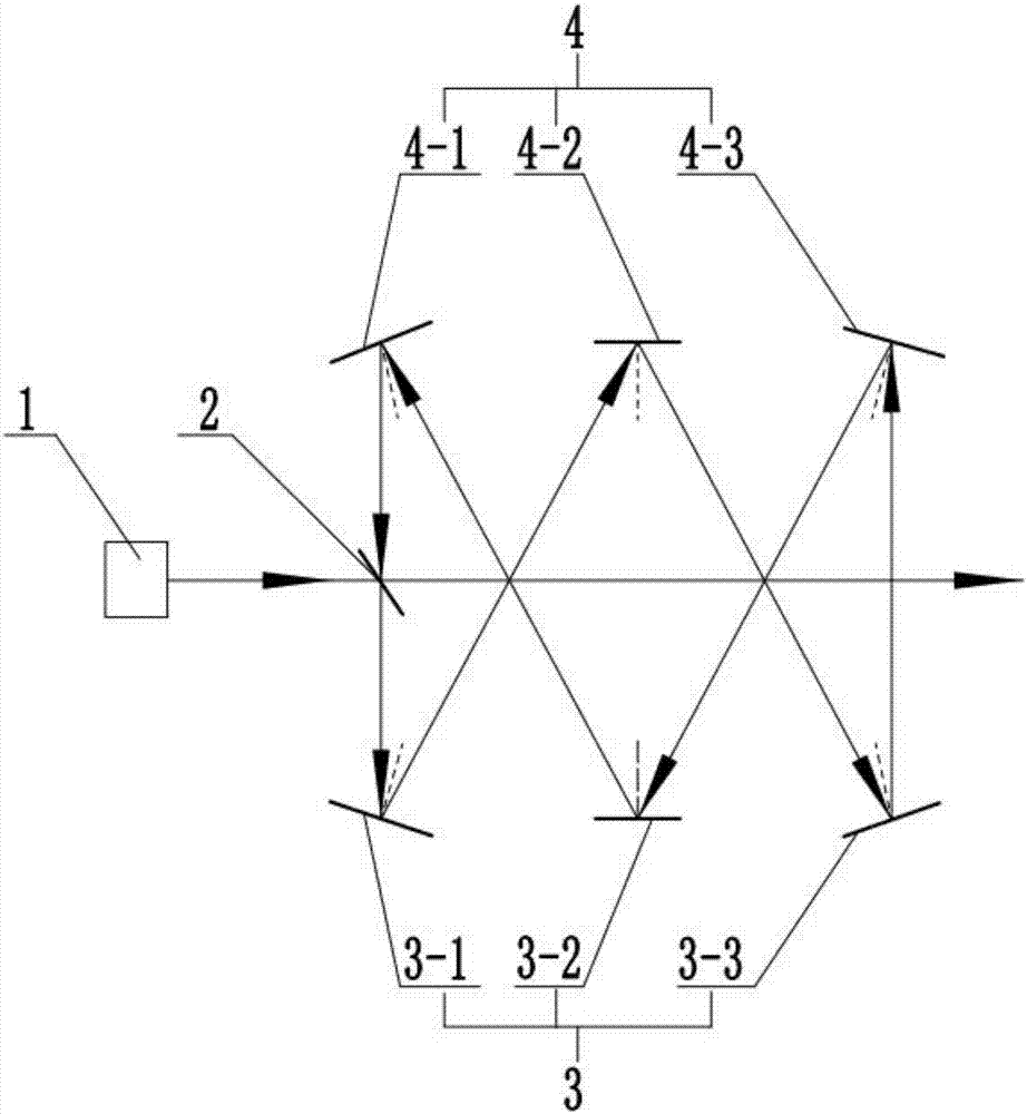
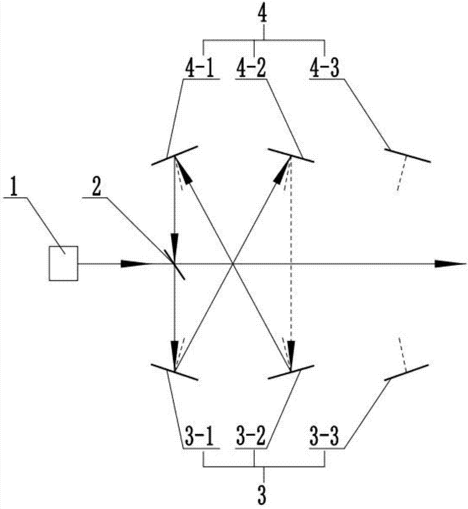
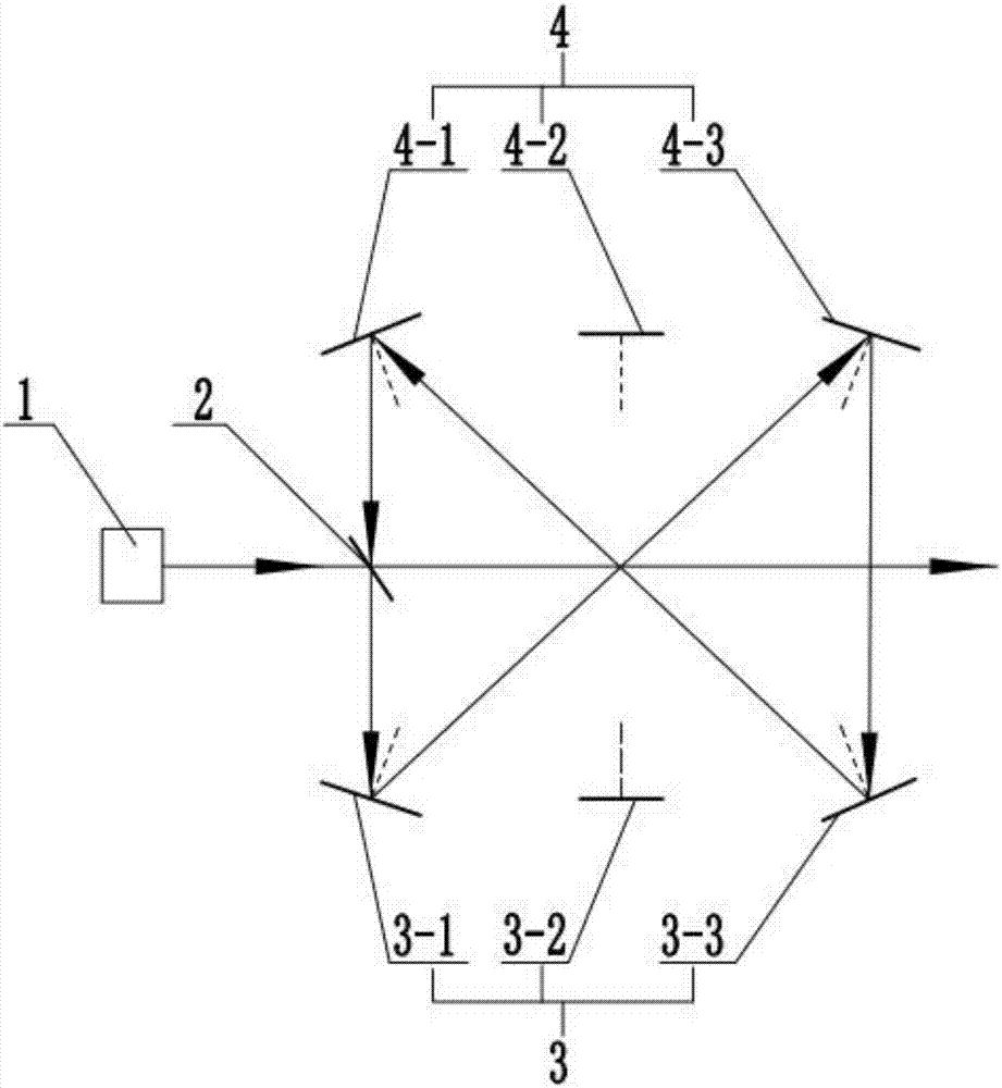
[0032] Such as figure 1 As shown, the present invention provides a device for changing the light pulse waveform, which includes: a light source 1, a half mirror 2 arranged on the light incident direction of the light source 1, and side by side mirrors arranged on both sides of the light incident direction The first reflective element 3 and the second reflective element 4 .

[0033] In this embodiment, there are at least two first reflective elements 3 and at least two second reflective elements 4; the reflection angles of the first reflective elements 3 and the second reflective elements 4 are both adjustable.

[0034] Such as figure 1 As shown, a half mirror 2 is arranged in the light incident direction of the light source 1, specifically, the half mirror 2 is a half mirror beam splitter. On both sides of the light incident direction of the light source, three first ref...


PUM


Abstract

The invention relates to a device for changing optical pulse waveform, relates to the technical field of photoelectricity, and is to solve the technical problems of single optical pulse waveform, multiple replacement of parts and inconvenient use and the like in the prior art. The device for changing optical pulse waveform comprises a light source, a half-transparent and half-reflecting mirror, first reflection elements and second reflection elements. The first reflection element and the second reflection element can form larger optical path difference within a confined space, and by changing reflection angles of the first reflection elements and the second reflection elements respectively, a plurality of reflection beam optical path difference can be obtained, so that a reflection beam of the half-transparent and half-reflecting mirror is allowed to be mixed with a transmitting beam of the half-transparent and half-reflecting mirror after being subjected to multiple reflections of the first reflection elements and the second reflection elements, a plurality of pulse waveforms different from the original waveform can be obtained, and the purpose of changing the pulse waveform is achieved.

Description

technical field [0001] The invention relates to the field of optoelectronic technology, in particular to a device for changing the waveform of light pulses. Background technique [0002] Currently, a pulse wave refers to a sudden electrical signal that is intermittent and of very short duration. Any intermittent voltage or current is called pulse voltage or pulse current. In terms of telecommunication waveforms, except for sine waves and continuous waves composed of several sine components, they can all be called pulse waves. Common pulse waves include rectangular wave, sawtooth wave, triangular wave, spike wave, and staircase wave. Different waveforms can produce different applications. [0003] At present, different waveforms can be formed by superimposing two or more optical pulses of the same waveform with a time delay, so as to achieve the purpose of changing the optical pulse waveform, but the following defects exist in the traditional waveform changing device: the o...

Claims


Application Information

Patent Timeline
IPC IPC(8): G02B17/02G02B17/06
Inventor 李子健
Owner WUHAN CHINA STAR OPTOELECTRONICS TECH CO LTD
Why Eureka
Try Eureka