Electrowetting device and preparation method thereof

An electrowetting and device technology, applied in the field of electrowetting, can solve the problems of hydrophilic and hydrophobic modification of the support column, affecting the display effect, and the hydrophilicity and hydrophobicity cannot be further improved. Effect

Inactive Publication Date: 2017-11-24
SHENZHEN GUOHUA OPTOELECTRONICS +2
View PDF2 Cites 2 Cited by
  • Summary
  • Abstract
  • Description
  • Claims
  • Application Information

AI Technical Summary

Problems solved by technology

[0003] At present, LCD and other display processes often use inorganic or organic particles to support the device, but for electrowetting devices, if the particle support column is sprinkled into the ink 5 in the display area, the display effect will be affected, so it is not recommended use
In the electrowetting device, some patents propose that after the packaging is completed, in-situ polymerization is carried out by exposure to form the polymer support pillars, but in this way, all packaging processes of the device must be completed under yellow light conditions before in-situ polymerization. , and the hydrophilicity and hydrophobicity cannot be further improved
There is also a patent to prepare photoresist support pillars by secondary photolithography at the intersection of pixel walls, but the photoresist material limits the hydrophilicity and hydrophobicity of the support pillars, and the support pillars of this method cannot be further hydrophilic and hydrophobic. Modified, and the hydrophobic support column will attract ink, so the support column needs to have a very high hydrophilicity

Method used


Image

  • Electrowetting device and preparation method thereof
  • Electrowetting device and preparation method thereof
  • Electrowetting device and preparation method thereof

Examples


Embodiment Construction

[0036] The present invention will be further described below with reference to specific embodiments.

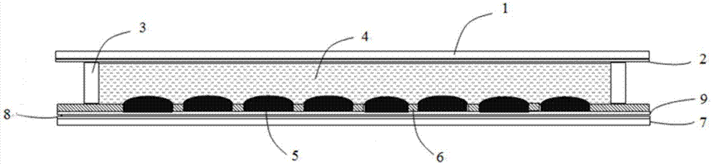
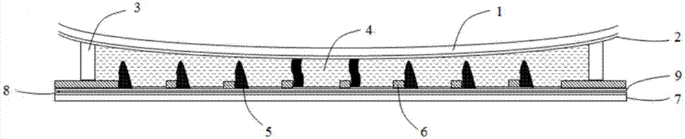
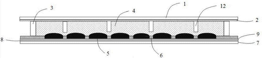
[0037] image 3 The schematic structural diagram of the electrowetting display device with the support column structure of the present embodiment, the main structure consists of the upper substrate, the lower substrate, and two immiscible polar electrolyte solutions 4 and Non-polar solution 5 composition. The upper substrate consists of an upper support plate 1 , a first electrode 2 , a sealant frame 3 , and a support column 12 , and the lower substrate consists of a lower support plate 7 , a second electrode 8 , a hydrophobic insulating layer 9 , and a pixel wall 6 .

[0038] The support column 12 is directly formed on the upper substrate 2 by physical etching or photolithography, and the shape of the support column structure 12 is a cylindrical or polygonal column structure. When the support column structure 12 is aligned with the lower substrate, in the preferred solutio...


PUM


Abstract

The invention belongs to the field of electrowetting, and discloses an electrowetting device. The electrowetting device includes an upper substrate and a lower substrate; a cavity formed by the opposite upper and lower substrates is filled with encapsulation liquid; the upper substrate includes an upper support plate, a first electrode, a sealing plastic frame and support columns; the lower substrate includes a lower support plate, a second electrode, a hydrophobic insulation layer and a pixel wall. The invention further discloses a preparation method of the electrowetting device. According to the electrowetting device, the support column structure is arranged on the upper substrate, which is different from other electrowetting devices of which support columns are arranged on the lower substrate, the support column on the upper substrate can be subjected to several kinds of physical and chemical hydrophilic modifications, so that the support column achieves the conditions of super hydrophilicity and super oleophobicity, and therefore the influence of the support column on ink movement is greatly reduced.

Description

technical field [0001] The invention belongs to the field of electrowetting, in particular to an electrowetting device and a preparation method thereof. Background technique [0002] The basic structure of electrowetting display device is as follows figure 1 As shown, it is composed of two immiscible polar electrolyte liquids 4 and non-polar liquids 5 filled in the sealed cavity formed by the upper and lower substrates and the two substrates facing each other, wherein the upper substrate is composed of the upper support plate 1, the first The electrode 2 and the sealant frame 3 are composed, and the lower substrate is composed of a lower support plate 7 , a second electrode 8 , a hydrophobic insulating layer 9 and a pixel wall 6 . from figure 1 It can be seen from the structure that the non-polar liquid 5 is uniformly filled in the pixel grid enclosed by the pixel wall 6. Since the material of the pixel wall 6 is hydrophilic, the adjacent non-polar solution 5 is cut off by...

Claims


Application Information

Patent Timeline
Patent Type & Authority Applications(China)
IPC IPC(8): G02B26/00
CPCG02B26/005
Inventor 唐彪窦盈莹水玲玲李瑞智蒋洪伟李辉郭媛媛周蕤李发宏艾利克斯·汉森·维克多周国富
Owner SHENZHEN GUOHUA OPTOELECTRONICS
Why Eureka
Try Eureka