
A signal input circuit and a hot-swappable optical module

A signal input circuit and signal input technology, applied in the electronic field, can solve problems such as lowering the potential of the system board, damaging the single-chip microcomputer, and lowering the I potential of the signal input pin, so as to prevent overvoltage damage

Active Publication Date: 2019-09-20
HISENSE BROADBAND MULTIMEDIA TECH
View PDF9 Cites 0 Cited by
  • Summary
  • Abstract
  • Description
  • Claims
  • Application Information

AI Technical Summary

Problems solved by technology

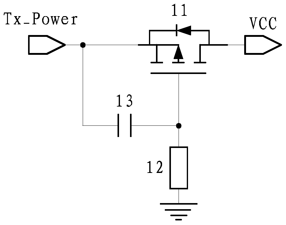
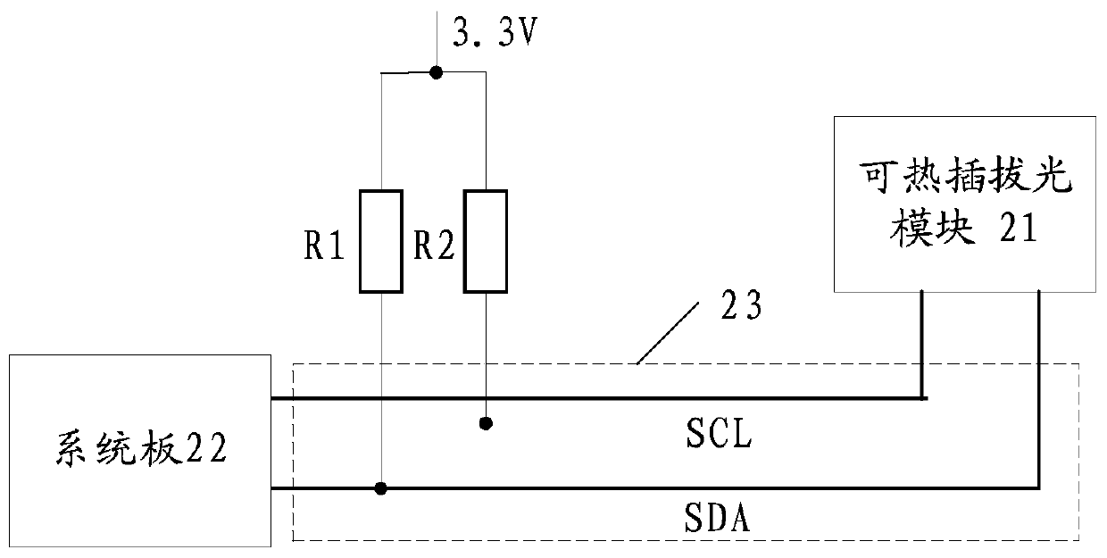
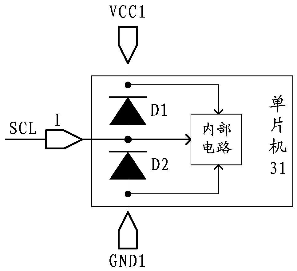
The structure of the above-mentioned hot-swappable optical module has the following defects: After the hot-swappable optical module 21 is inserted and before the transistor 11 of the slow power-on circuit is turned on, the internal circuit of the single-chip microcomputer of the hot-swappable optical module and the ground The impedance between them is small, that is, the impedance between the cathode of the upper diode D1 of the clamping circuit and the ground is small, and the power supply pin VCC1 of the single-chip microcomputer will be connected between VCC1 and GND1 through the internal circuit of the single-chip microcomputer and other circuits inside the optical module. Discharge to the ground, thereby pulling down the potential of the signal input pin I and the potential of the IIC of the system board. At this time, other devices connected to the IIC of the system board will mistakenly think that the pluggable optical module will occupy the IIC of the system board , so that the IIC of the system board cannot be used normally, and if the clamp circuit on each signal input pin of the microcontroller is removed, the voltage input to the microcontroller will not be limited, so it may cause overvoltage damage to the microcontroller

Method used


Image

  • A signal input circuit and a hot-swappable optical module
  • A signal input circuit and a hot-swappable optical module
  • A signal input circuit and a hot-swappable optical module

Examples


Embodiment Construction

[0022] The following will clearly and completely describe the technical solutions in the embodiments of the present invention with reference to the accompanying drawings in the embodiments of the present invention. Obviously, the described embodiments are only some, not all, embodiments of the present invention. Based on the embodiments of the present invention, all other embodiments obtained by persons of ordinary skill in the art without making creative efforts belong to the protection scope of the present invention.

[0023] The transistors used in all the embodiments of the present invention can be thin film transistors or field effect transistors or other devices with the same characteristics. According to the function in the circuit, the transistors used in the embodiments of the present invention mainly function as switches. Since the source and drain of the transistors used here are symmetrical, their source and drain are interchangeable. In the embodiment of the prese...


PUM


Abstract

The invention provides a signal input circuit and a hot-swappable optical module, which relate to the field of electronic technology and are used for avoiding lowering the potential of a signal input pin of the single-chip microcomputer while preventing overvoltage from damaging the single-chip microcomputer. The circuit includes: a control module and a clamping module; the control module is connected to the power supply, the ground pin of the single-chip microcomputer and the first level terminal, and is used to output the voltage of the first level terminal to the ground of the single-chip microcomputer under the control of the working voltage output by the power supply Pin, when the power supply does not output the working voltage, the ground pin of the microcontroller is controlled to float; the upper voltage terminal of the clamp module is connected to the power supply pin of the microcontroller, and the lower voltage terminal of the clamp module is connected to the ground pin of the microcontroller; Under the control of the voltage of the upper voltage terminal and the voltage of the lower voltage terminal, the voltage of the input signal input to the single-chip microcomputer through the signal input pin of the single-chip microcomputer is clamped. The invention is used for the manufacture of hot pluggable optical modules.

Description

technical field [0001] The invention relates to the field of electronic technology, in particular to a signal input circuit and a hot-swappable optical module. Background technique [0002] Hot plugging (English name: hot-plugging or Hot Swap) is live plugging. Hot-swappable devices allow users to take out or plug in without shutting down the system or cutting off the power supply. Therefore, hot-swappable devices have high flexibility and have a wide range of application prospects. [0003] The hot-swappable optical module in the prior art has a slow power-on circuit for reducing the impact on the system power supply. Specifically, refer to figure 1 In the slow power-on circuit shown, when the system power supply Tx_Power inputs voltage, the input voltage first charges capacitor 13, so that the voltage on the gate of transistor 11 gradually decreases from high to zero, transistor 11 is slowly turned on, and then Power is provided to the hot-swappable optical module throug...

Claims


Application Information

Patent Timeline
Patent Type & Authority Patents(China)
IPC IPC(8): G06F13/40H03K19/0185
Inventor 赵伟徐海强崔伟
Owner HISENSE BROADBAND MULTIMEDIA TECH
Learn More