Three-dimensional modeling method of side-pushing structure

A 3D modeling and 3D model technology, applied in special data processing applications, instruments, electrical digital data processing, etc., can solve the problems of long assembly time, difficult deployment, poor aesthetic effect, etc., to ensure performance and aesthetics, reduce Production cost, the effect of improving work efficiency

Active Publication Date: 2017-11-24
CSSC HUANGPU WENCHONG SHIPBUILDING COMPANY
View PDF2 Cites 19 Cited by
  • Summary
  • Abstract
  • Description
  • Claims
  • Application Information

AI Technical Summary

Problems solved by technology

[0004] The present invention aims at the disadvantages of manual lofting and unfolding of the side thruster structure in the prior art, such as high dif

Method used


Image

  • Three-dimensional modeling method of side-pushing structure
  • Three-dimensional modeling method of side-pushing structure
  • Three-dimensional modeling method of side-pushing structure

Examples


Embodiment Construction

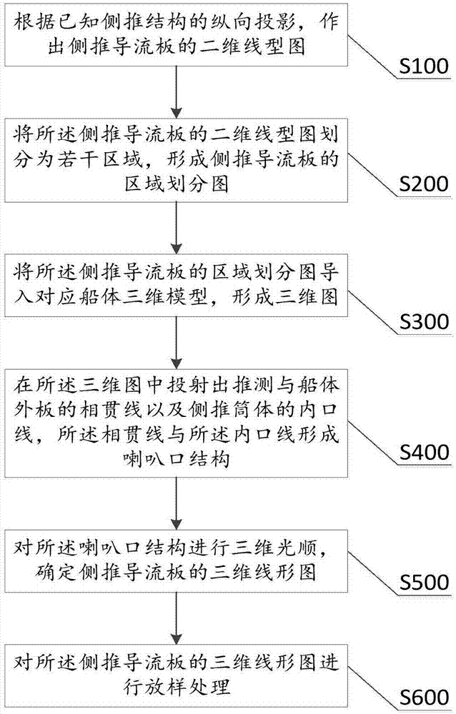
[0029] The specific implementation manners of the present invention will be further described in detail below in conjunction with the accompanying drawings and embodiments. The following examples are used to illustrate the present invention, but are not intended to limit the scope of the present invention.

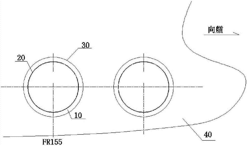
[0030] Such as figure 2 Shown is the design requirement diagram of the hull side thrust structure, which is represented by figure 2 It can be seen that the transition between the side thruster structure and the outer plate of the hull is an irregular curved surface, and those skilled in the art call the transition surface formed by the side thruster structure and the outer plate of the hull a side thruster deflector 10 . For the processing and manufacturing of the side thrust deflector 10 , it is necessary to carry out lofting and unfolding for dimension measurement. At present, the lofting and unfolding of the side thrust deflector 10 mainly relies on traditional manua...


PUM


Abstract

The invention relates to a three-dimensional modeling method of a side-pushing structure. The method comprises the following steps: A, making a two-dimensional line graph of a side-pushing flow guide plate along projection of a shaft line direction in the side-pushing structure according to a three-dimensional model of the known side-pushing structure; B, dividing the two-dimensional line graph of the side-pushing flow guide plate into a plurality of regions to form a region division graph of the side-pushing flow guide plate; C, importing the region division graph of the side-pushing flow guide plate to a corresponding three-dimensional hull model to form a three-dimensional graph; D, projecting an intersecting line of the side-pushing structure and an outer plate of a hull and an inner mouth line of a side-pushing cylinder in the three-dimensional graph, wherein the intersecting line and the inner mouth line forms a horn mouth structure; E, carrying out three-dimensional fairing on the horn mouth structure, and determining a three-dimensional line graph of the side-pushing flow guide plate; and F, carrying out lofting processing on the three-dimensional line graph of the side-pushing flow guide plate. According to the method provided by the invention, jointing transition of the side-pushing structure and the outer plate can be intuitively adjusted, fairing connection of the side-pushing structure and the outer plate of the hull is ensured, and the performance and the beauty of the side-pushing structure are ensured.

Description

technical field [0001] The invention relates to the field of hull structures, in particular to a three-dimensional modeling method for hull side thrust structures. Background technique [0002] At present, the lofting and unfolding of hull side thruster structures such as side thruster deflectors mainly rely on traditional manual lofting techniques. The disadvantages of manual lofting are time-consuming, large errors, and low precision. Especially for the side thruster structure with complex structure, it is more difficult to ensure the accuracy of the lofted parts. Often, the lack of manual lofting is made up for by adding margins to the parts. Make sure the dimensions of the parts. This increases the material cost and reduces the utilization rate of the plate. [0003] In addition, the side thruster structural parts that are manually lofted and unfolded need to be trimmed and corrected, resulting in a longer assembly cycle, and the transition connection between the parts...

Claims


Application Information

Patent Timeline
IPC IPC(8): G06F17/50
CPCG06F30/15G06F30/20
Inventor 杨伟锋杨秀峰曾建坤王碧涛
Owner CSSC HUANGPU WENCHONG SHIPBUILDING COMPANY
Why Eureka
Try Eureka