
Wiring method of wiring terminal

A terminal and wiring method technology, applied in the direction of connection, line/collector parts, electrical components, etc., can solve the problems of waste of resources, corrosion of paint film, poor ductility and hardness of aluminum wire, etc., and reduce gas and dust Emissions, avoiding environmental damage and improving production efficiency

Active Publication Date: 2017-11-24
FOSHAN SHUNDE MIDEA ELECTRICAL HEATING APPLIANCES MFG CO LTD +1
View PDF5 Cites 4 Cited by
  • Summary
  • Abstract
  • Description
  • Claims
  • Application Information

AI Technical Summary

Problems solved by technology

[0003] 1. The terminal riveting needs to go through at least 4 processes such as paint stripping, riveting, dipping flux, dipping tin, etc. The process is complicated and the efficiency is low
[0004] 2. The paint film on the surface of the enameled wire is generally removed by a paint remover or a paint remover. The paint removal efficiency of the paint remover is low, and the ductility and hardness of the aluminum wire after paint removal are poor; the paint remover removes the paint film It is easy to break the enameled wire, which will affect the resistance value of the coil disk and cause waste of resources
[0005] 3. The enameled wire needs to be dipped in flux before it is fixedly connected with the tin on the terminal. The flux is corrosive to a certain extent, which will cause corrosion of the paint film on other parts of the enameled wire that do not need to be removed, and eventually lead to oxidation of the enameled wire, which is easy to break when bent. wire, which affects the resistance value and service life of the coil disc

Method used


Image

  • Wiring method of wiring terminal
  • Wiring method of wiring terminal
  • Wiring method of wiring terminal

Examples


Embodiment Construction

[0034] The principles and features of the present invention are described below in conjunction with the accompanying drawings, and the examples given are only used to explain the present invention, and are not intended to limit the scope of the present invention.

[0035] A terminal wiring method in this embodiment includes the following steps:

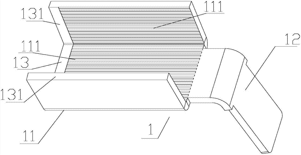
[0036] SO, set up a plurality of paint guide grooves 111 on the inner surface and the bottom surface of the crimping fixing groove 13;

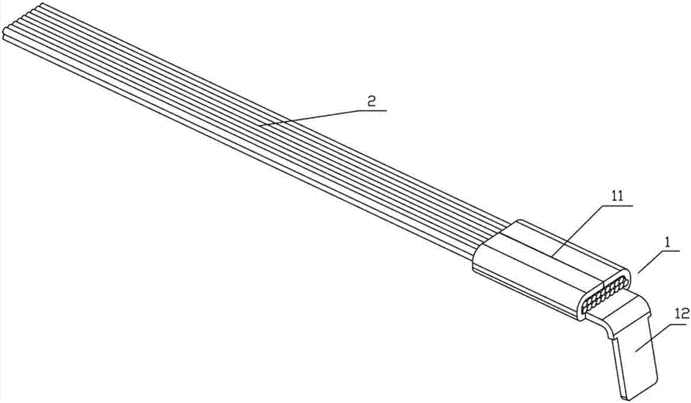
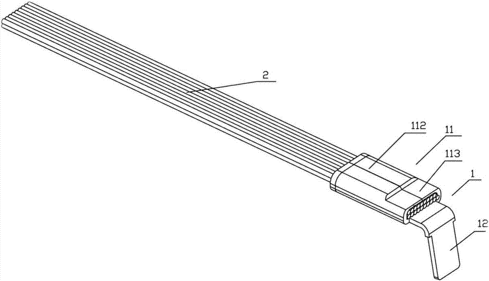
[0037] S1, put the outlet end of enameled wire 2 into figure 1 In the crimping fixing groove 13 of the unformed terminal 1, the side wall 131 of the crimping fixing groove 13 is extruded at least once at room temperature by terminal riveting equipment, so that the enameled wire is fixed on the connecting terminal 1, and the enameled wire The fastening force between 2 and the terminal 1 is greater than or equal to 10N, so as to ensure that the enameled wire 2 is fixedly connected to the terminal 1; ...


PUM


Abstract

The invention relates to a wiring method of a wiring terminal. The wiring method comprises the following steps of S1, putting a varnished wire into a crimping and fixing groove of the wiring terminal, and performing at least one time of normal-temperature extrusion on the side wall of the crimping and fixing groove to enable the varnished wire to be fixedly connected with the wiring terminal; and S2, performing at least one time of high-temperature extrusion on the side wall of the crimping and fixing groove to enable the varnished wire to be electrically conducted with the wiring terminal. Compared with the conventional process, normal-temperature extrusion for fixation and high-temperature extrusion for conduction are carried out by the wring method disclosed in the invention, so that the varnished film of the varnished wire can be molten through high-temperature extrusion, and the conduction effect between the varnished wire and the wiring terminal can be reinforced; and in addition, production efficiency is improved, production cost is lowered, emission of gases and powder with pungent smell can be reduced, and damage to the environment and harm to the body of an operator can be avoided.

Description

technical field [0001] The invention relates to the technical field of small household appliances, in particular to a terminal connection method. Background technique [0002] The connection process between the aluminum enameled wire and the terminal of the existing coil coil is that the aluminum enameled wire is first stripped of the paint film, and then cold-pressed and riveted on the terminal. Terminal blocks for stable connections. This terminal riveting process has the following defects: [0003] 1. The terminal riveting needs to go through at least 4 processes such as paint stripping, riveting, dipping flux, dipping tin, etc. The process is complicated and the efficiency is low. [0004] 2. The paint film on the surface of the enameled wire is generally removed by a paint remover or a paint remover. The paint removal efficiency of the paint remover is low, and the ductility and hardness of the aluminum wire after paint removal are poor; the paint remover removes the ...

Claims


Application Information

Patent Timeline
Patent Type & Authority Applications(China)
IPC IPC(8): H01R43/048
CPCH01R43/048
Inventor 范吉昌任玉洁蒙剑友易亮何田田吴金华张翼飞
Owner FOSHAN SHUNDE MIDEA ELECTRICAL HEATING APPLIANCES MFG CO LTD
Learn More