
Control circuit, control method and switching power supply

A switching power supply and control circuit technology, applied in the direction of electrical components, output power conversion devices, etc., can solve the problems of duty cycle limitation of driving signals, switching power supply is difficult to maintain output voltage, etc., and achieve the effect of preventing false triggering

Active Publication Date: 2017-11-24
SILERGY SEMICON TECH (HANGZHOU) CO LTD
View PDF6 Cites 1 Cited by
  • Summary
  • Abstract
  • Description
  • Claims
  • Application Information

AI Technical Summary

Problems solved by technology

Due to the existence of the minimum off time, in the switching power supply controlled by fixed frequency, the duty cycle of the driving signal of the main switching tube will be limited, and the higher the switching frequency of the main switching tube, this limitation will be more obvious
For example, for a step-down switching power supply, when the output voltage is required to be relatively close to the input voltage, the duty cycle of the driving signal of the main switch tube needs to be as close to 1 as possible. However, the existing fixed frequency control method, Due to the existence of the minimum off time, the maximum duty cycle of the driving signal of the main switch is limited and cannot be further expanded, making it difficult for the switching power supply to maintain the required output voltage

Method used


Image

  • Control circuit, control method and switching power supply
  • Control circuit, control method and switching power supply
  • Control circuit, control method and switching power supply

Examples


Embodiment Construction

[0043] The following will clearly and completely describe the technical solutions in the embodiments of the present invention with reference to the accompanying drawings in the embodiments of the present invention. Obviously, the described embodiments are only some, not all, embodiments of the present invention. Based on the embodiments of the present invention, all other embodiments obtained by persons of ordinary skill in the art without making creative efforts belong to the protection scope of the present invention. In addition, it should be noted that "the..." in the content of the specific embodiment only refers to the technical attributes or characteristics of the present invention.

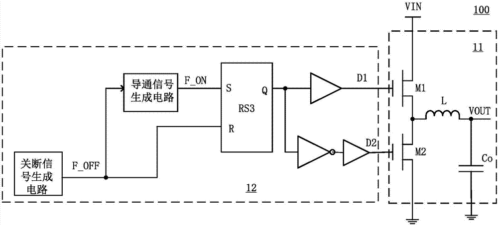
[0044] figure 1 It is a schematic structural diagram of a switching power supply 100 according to an embodiment of the present invention. The switching power supply 100 is mainly composed of a power stage circuit 11 and a control circuit 12 . The control circuit 12 controls the switch sta...


PUM


Abstract

The invention provides a control circuit, a control method and a switching power supply. A frequency for controlling a conduction signal conducted by a main switch tube is a preset frequency when a switch-off time required by the main switch tube is larger than minimum switch-off time and is a frequency positively related to the switch-off time required by the main switch tube when the switch-off time required by the main switch tube is smaller than the minimum switch-off time, so that smooth switching between a fixed-frequency working mode and a variable frequency fixed switch-off working mode can be achieved, a mode switching signal is provided without a special mode judgment circuit, the control circuit is simple in implementation mode, and the expansion of a duty ratio of a switch control signal of the main switch tube can be stably and continuously achieved; and moreover, during the frequency conversion process, the power supply is still in the constant switch-off time working mode, so that the problem of subharmonic oscillation caused by insufficient subharmonic compensation due to frequency conversion is prevented.

Description

technical field [0001] The invention relates to the technical field of power electronics, and in particular relates to a control circuit, a control method and a switching power supply. Background technique [0002] Switching power supplies are widely used in portable electronic devices, and they are mainly composed of power stage circuits and control circuits. The control circuit controls the switching power supply to convert the input voltage into a corresponding output voltage by controlling the duty ratio of the driving signal of the main switching tube in the power stage circuit. [0003] Based on the inherent delay in the logic circuit and the driving circuit in the switching power supply, and in order to prevent false triggering of the main switching tube, it is usually necessary to make the main switching tube of the switching power supply have a minimum off time. Due to the existence of the minimum off time, in the switching power supply controlled by fixed frequenc...

Claims


Application Information

Patent Timeline
IPC IPC(8): H02M1/00
CPCH02M1/00H02M1/0003
Inventor 陈君
Owner SILERGY SEMICON TECH (HANGZHOU) CO LTD
Learn More