Gyromagnetic radial tension-compression excited piezoelectric generator

A generator and piezoelectric technology, applied in the direction of generator/motor, piezoelectric effect/electrostrictive or magnetostrictive motor, electrical components, etc. Limited space and other issues, to achieve the effect of simple structure and manufacturing process, controllable range of compressive stress, and high reliability

Pending Publication Date: 2017-11-24
ZHEJIANG NORMAL UNIVERSITY
View PDF10 Cites 0 Cited by
  • Summary
  • Abstract
  • Description
  • Claims
  • Application Information

AI Technical Summary

Problems solved by technology

[0002] In order to meet the power supply requirements of helicopter propellers, automobile tires, aeroengines, high-speed trains, oil and gas drills, gears and other rotating bodies or their bearing components health monitoring systems, scholars at home and abroad have proposed various forms of rotationally excited piezoelectric generators. The common feature is that the single transducer is used as the energy conversion device, the amount of deformation cannot be controlled, and the piezoelectric material is subjected to alternating tension-compression stress during work.
Since the deformation of the single transducer cannot be controlled, and the allowable tensile stress of the piezoelectric ceramic material is far

Method used


Image

  • Gyromagnetic radial tension-compression excited piezoelectric generator
  • Gyromagnetic radial tension-compression excited piezoelectric generator
  • Gyromagnetic radial tension-compression excited piezoelectric generator

Examples


Example Embodiment

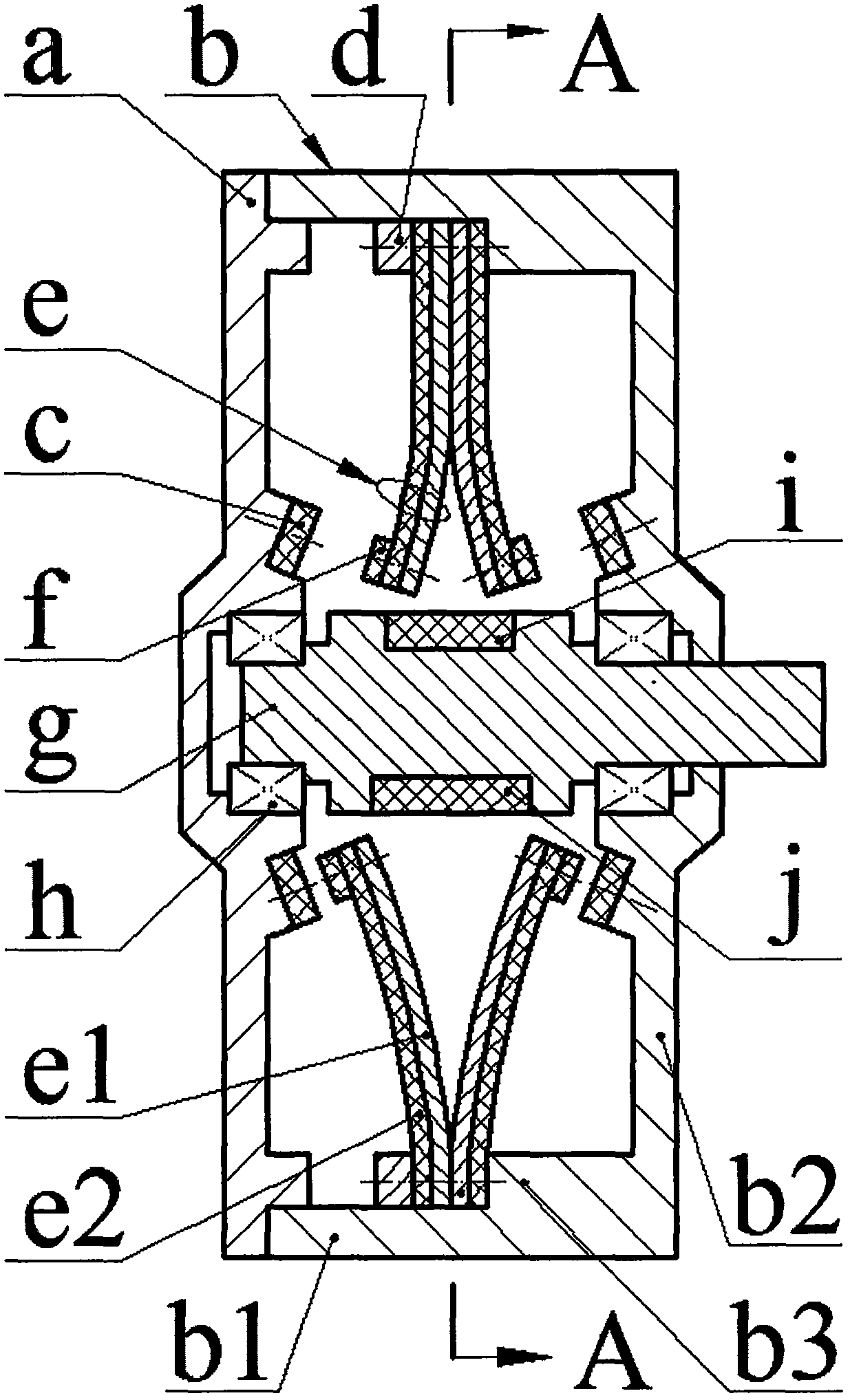
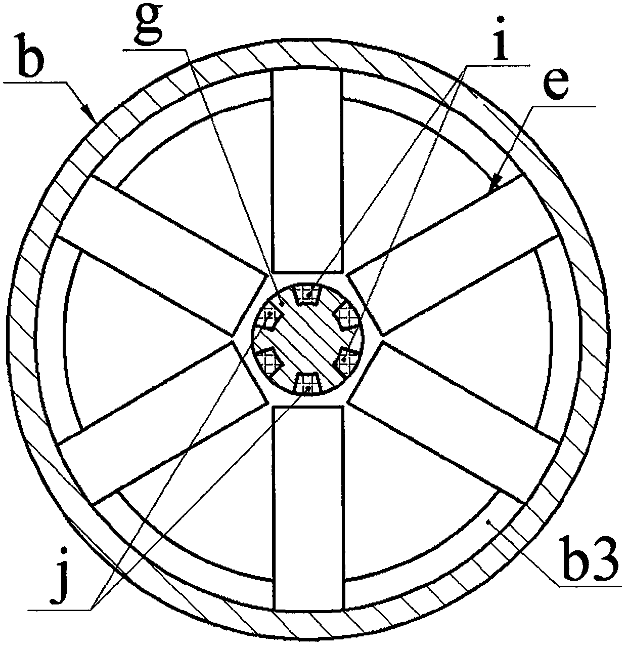
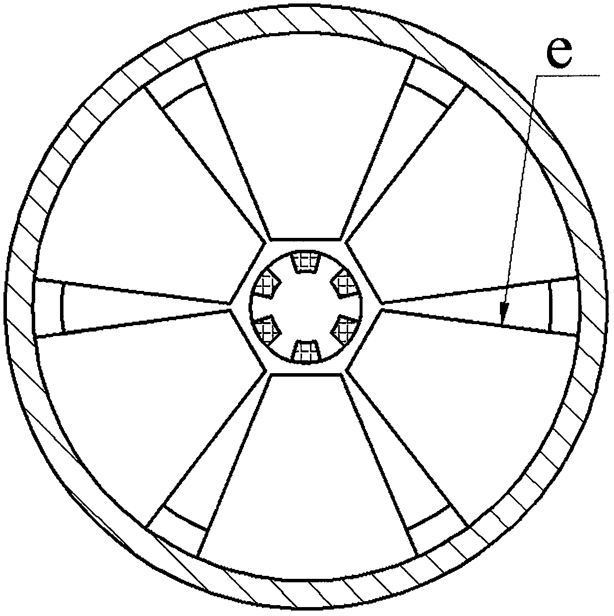
[0010] The end cover a is installed on the end of the cylinder wall b1 of the shell b by screws, and the limit magnet c is installed on the end cover a and the bottom wall b2 of the shell by screws; the cylinder wall boss b3 is installed with screws and pressure ring d Two sets of transducers e, the transducer e is formed by bonding the substrate e1 and the piezoelectric sheet e2, the two sets of transducers e are installed symmetrically and their substrates e1 are in contact with each other; the free end piezoelectric sheet e2 of the transducer e One side is screwed with the excited magnet f. The excited magnet f is installed opposite to the same poles of the adjacent limit magnet c. The two sets of excited magnets f have the same poles opposite to each other and the repulsive force between them makes the transducer e Bending deformation occurs; the left and right ends of the main shaft g are respectively installed on the end cover a and the bottom wall b2 of the shell through ...


PUM


Abstract

The invention relates to a gyromagnetic radial tension-compression excited piezoelectric generator, and belongs to the technical field of piezoelectric power generation. An end cover is mounted at the end of a cylindrical wall of a shell, and limiting magnets are mounted on the end cover and the bottom wall of the shell; two groups of transducers are mounted on a cylindrical wall boss, the transducer is formed by sticking a substrate with piezoelectric plates, the two groups of transducers are symmetrically mounted and the substrates thereof contact each other; an excited magnet is mounted on one side of the piezoelectric plate at the free end of each transducer, the excited magnet is mounted opposite to the same magnetic pole of the adjacent limiting magnet, and the two groups of excited magnets are mounted with the same magnetic poles opposite; the left and right ends of a main shaft are respectively mounted on the end cover and the bottom wall of the shell via bearings, one end of the main shaft extends out via the bottom wall of the shell, exciting magnets I and I are uniformly embedded into the circumference of the main shaft and configured at intervals, and the exciting magnets I and I are arranged using the contact faces of the fixed ends of the two groups of transducers as axial symmetry centers; the exciting magnets I attract the excited magnets, and the exciting magnets II dispel the excited magnets.

Description

technical field [0001] The invention belongs to the technical field of new energy and power generation, and in particular relates to a piezoelectric generator with gyromagnetic radial tension and pressure excitation, which is used for power supply of a health monitoring system of a rotating body. Background technique [0002] In order to meet the power supply requirements of helicopter propellers, automobile tires, aeroengines, high-speed trains, oil and gas drills, gears and other rotating bodies or their bearing components health monitoring systems, scholars at home and abroad have proposed various forms of rotationally excited piezoelectric generators. The common feature is that a single transducer is used as an energy conversion device, the amount of deformation cannot be controlled, and the piezoelectric material is subjected to alternating tension-compression stress during operation. Since the deformation of the single transducer cannot be controlled, and the allowable...

Claims


Application Information

Patent Timeline
IPC IPC(8): H02N2/18
CPCH02N2/18
Inventor 张忠华费翔王淑云
Owner ZHEJIANG NORMAL UNIVERSITY
Why Eureka
Try Eureka