A Gradual Excited Piezoelectric Fluid Generator

A generator and fluid technology, applied in the direction of generator/motor, piezoelectric effect/electrostrictive or magnetostrictive motor, electrical components, etc. The effect of strong fluid adaptability, improved power generation capacity, and high reliability

Active Publication Date: 2019-02-15
重庆凯纳机电有限公司
View PDF5 Cites 0 Cited by
  • Summary
  • Abstract
  • Description
  • Claims
  • Application Information

AI Technical Summary

Problems solved by technology

Although some of the pipeline fluid leakage and anti-theft monitoring and alarm methods proposed are relatively mature at the technical level, the application of the anti-theft monitoring system for long-distance pipelines in my country is still in its infancy and has not yet been widely used. One of the main reasons is The power supply problem of the monitoring system has not been well solved: ①The cost of laying cables is high and it is easy to be cut off by criminals, which will affect the normal operation of the monitoring system; ②The battery power supply has a limited service time and needs to be replaced frequently. The remote transmission of monitoring information cannot be completed even when it is replaced in time
In recent years, in order to meet the self-power supply requirements of related wireless sensor monitoring systems, people have proposed various forms of turbine-type micro-fluid power generation devices. The biggest problem is that the structure is complex and the volume is relatively large, which is not suitable for pipelines with small diameters. In some occasions, some structures of power generation devices still have electromagnetic interference and other phenomena, and their popularization and application are restricted to a certain extent.

Method used


Image

  • A Gradual Excited Piezoelectric Fluid Generator
  • A Gradual Excited Piezoelectric Fluid Generator
  • A Gradual Excited Piezoelectric Fluid Generator

Examples


Embodiment Construction

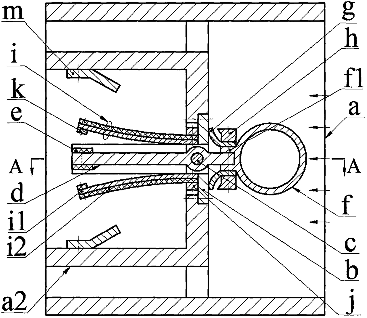
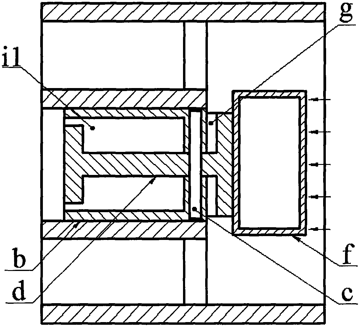
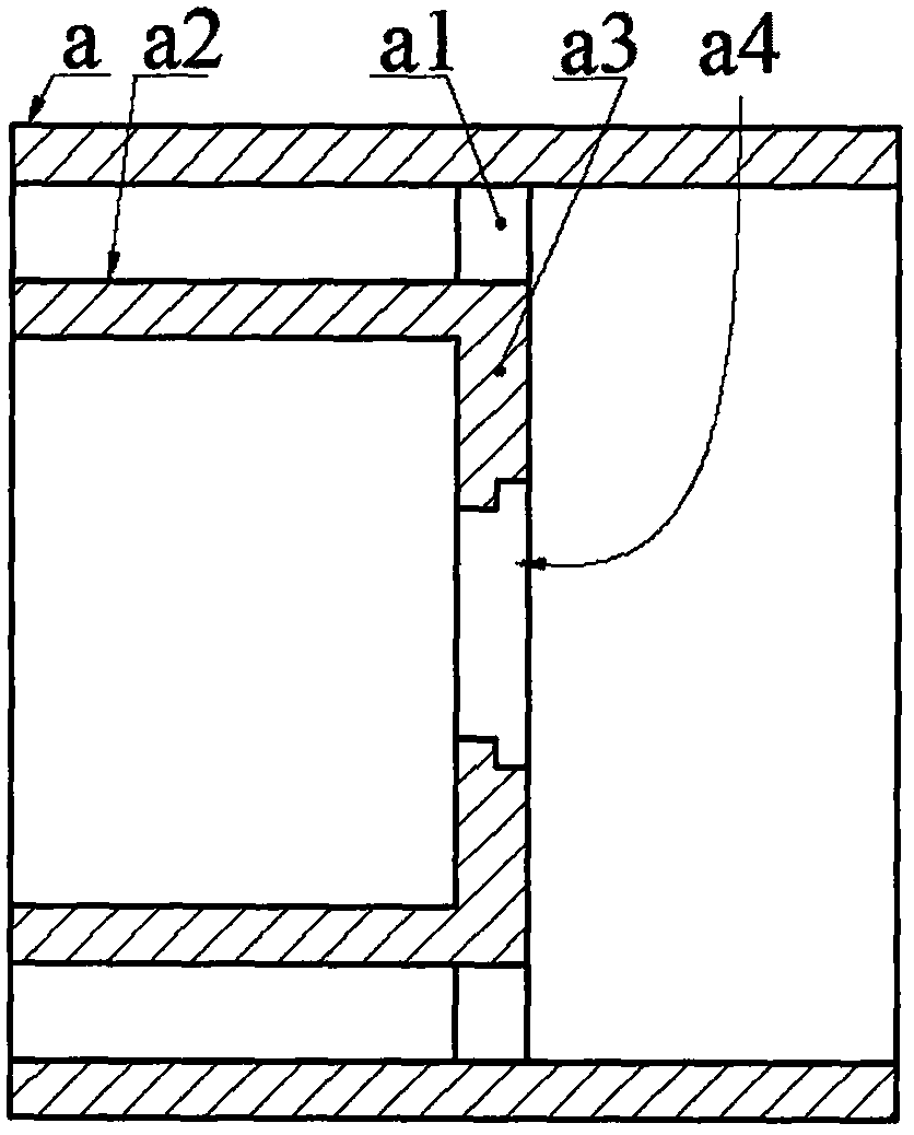
[0014] An inner cylinder a2 is installed on the inner wall of the pipe a through the ear plate a1, the cross section of the inner cylinder a2 is square, a square hole a4 is arranged on the bottom wall a3 of the inner cylinder a2, and a bracket is installed on the boss of the square hole a4 through screws b. There is a through hole b2, two bracket bosses b3 and two limit plates b5 on the bracket bottom plate b1, the through hole b2 is located at the center of the bracket bottom plate b1, and the two bracket bosses b3 are symmetrically distributed on the sides of the through hole b2 On both sides, coaxial pin holes b4 are provided on the two bracket bosses b3, and the pin shaft c is sleeved in the pin hole b4; the pin hole d1 of the lever d is set on the pin shaft c, and the lever d is connected to the Through the through hole b2, the left arm d2 of the lever is placed in the inner tube a2, the left arm d2 of the lever is longer than the right arm d3 of the lever, the end of the ...


PUM


Abstract

The invention relates to a step-by-step excitation type piezoelectric fluid generator, and belongs to the fluid generating field; a pipeline inner wall is provided with an inner cylinder through ear plates; the bottom wall of the inner cylinder is provided with a square hole; a square hole boss is provided with a support; the support base plate is provided with a through hole, two support bosses, and two limit plates; the two support bosses are provided with coaxial pinholes, and a pin shaft is sleeved in the pinholes; lever pinhole is sleeved on the pin shaft; the lever penetrates the through hole of the support base plate; the lever left arm is arranged in the inner cylinder; the lever left arm end portion is provided with a left crossbeam, and the lever right arm is provided with a right crossbeam; suspending magnets are arranged on the top and bottom sides of the left crossbeam; the right crossbeam is arranged between two wing plates of a bluff body, and fixed by screws; the two wing plates are provided with springs and limit blocks; the other end of the spring abuts against the support base plate; the support boss is provided with an energy transducer; the energy transducer end portion is provided with a suspended magnet; same-polarity magnetic poles of the suspended magnet and suspending magnet are arranged in opposite; a reed used for limiting the energy transducer is arranged on the inner cylinder inner wall through screws.

Description

technical field [0001] The invention belongs to the technical field of pipeline fluid power generation, and in particular relates to a step-by-step excitation piezoelectric fluid generator, which provides energy for a pipeline monitoring system. Background technique [0002] Due to corrosion, natural force majeure and human theft, long-distance pipelines for long-distance fluids such as oil and natural gas often leak during use. Frequent pipeline leakage not only causes huge economic losses, but also affects the surrounding natural environment. caused serious pollution. In the past, regular manual inspections were often used for maintenance. However, due to the long laying distance of oil and gas pipelines and the fact that they are often located in inaccessible or inaccessible places, it is difficult to detect leaks and maintain them in time by manual inspections. Therefore, various types of pipeline leakage monitoring and anti-theft systems have been proposed. Although s...

Claims


Application Information

Patent Timeline
Patent Type & Authority Patents(China)
IPC IPC(8): H02N2/18
CPCH02N2/185
Inventor 阚君武费翔王淑云
Owner 重庆凯纳机电有限公司
Why Eureka
Try Eureka