Machine tool with a support piece

A technology for supporting components and machine tools, which is applied in the direction of manufacturing tools, workbenches, portable motorized devices, etc.

Active Publication Date: 2017-11-28
FESTOOL GMBH
View PDF9 Cites 4 Cited by
  • Summary
  • Abstract
  • Description
  • Claims
  • Application Information

AI Technical Summary

Problems solved by technology

However, the arrangement of the adjustment mechanism between the guide elements cannot be realized in every power tool

Method used


Image

  • Machine tool with a support piece
  • Machine tool with a support piece
  • Machine tool with a support piece

Examples


Embodiment Construction

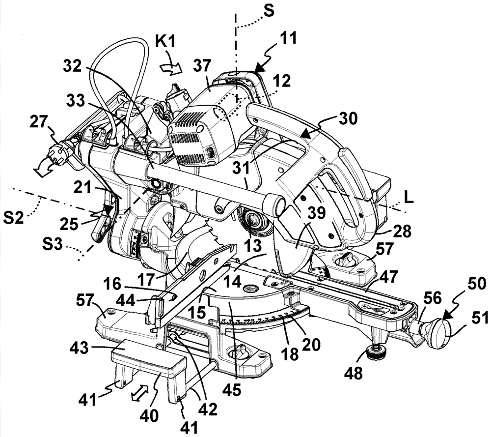
[0057] Machine tool 10 is designed, for example, as an oscillating saw. The drive assembly 11 of the power tool 10 comprises a drive motor 12 , which drives a tool receptacle 13 directly or via a transmission not shown, on which a detachable coupling can be arranged. Tool 14, such as a saw blade. The drive motor 12 is an electric drive motor, in particular a brushless drive motor.

[0058] The drive assembly 11 is arranged above a support surface 15 for supporting the workpiece W. As shown in FIG. The workpiece W can be placed on the support surface 15 and can be brought into contact with the contact surface 16 in order to carry out a separate cut by means of the separating tool 14 .

[0059] The bearing surface 15 is arranged on a pivot element 17 which is pivotable about a pivot axis S relative to a pivot base 18 . The pivot base 18 forms a machine base 20 .

[0060] The angular position of the tool receptacle 13 and thus the separating tool 14 relative to the abutment s...


PUM


Abstract

The invention relates to a machine tool (10) for machining workpieces with the aid of a tool. The machine tool (10) has a drive assembly arranged on a machine base (20). The drive assembly has a drive motor and a tool holder (13) for the tool. A support part (100) for supporting workpiece (W) or supporting the machine tool in the workpiece is vertically adjustably arranged on the machine base (20) through a vertical adjusting mechanism (101) relative to the vertical axis (VS). The vertical adjusting mechanism (101) comprises two rod like members namely a first guiding element and a second guiding element (42), which can move along the vertical axis (VS) and are supported by a first bearing component and a second bearing component (105 A, 105B) respectively.

Description

technical field [0001] The invention relates to a machine tool, in particular a mobile machine tool or a hand tool machine, for machining workpieces by means of a tool, wherein the machine tool has a drive assembly arranged on the machine base, the machine tool having The drive assembly has a drive motor and a tool receptacle drivable by the drive motor for the tool, in particular a separating tool, for supporting a workpiece on the power tool relative to the tool receptacle The supporting part or for supporting the power tool on the workpiece, in particular guided, is mounted on the machine base so that it can be adjusted longitudinally with respect to the longitudinal axis by means of a longitudinal adjustment mechanism, wherein the longitudinal adjustment mechanism has two parallel rod-shaped first and second guide elements extending along the longitudinal axis, said first and second guide elements being supported longitudinally displaceably along the longitudinal axis in t...

Claims


Application Information

Patent Timeline
Patent Type & Authority Applications(China)
IPC IPC(8): B23D47/02B27B5/20B25F5/00
CPCB23D47/02B23D47/025B25F5/00B27B5/20B25F5/021B25H1/0078
Inventor M.韦巴赫T.赫费尔
Owner FESTOOL GMBH
Why Eureka
Try Eureka