Feeding device of laser cutting machine

A laser cutting machine and laser machine technology, applied in the field of mechanical processing, can solve the problems of long working area of ​​laser cutting machinery, unfavorable work site planning, damage to the guide rail transmission structure, etc., and achieve safe and scientific working area, practical value, and convenient use. Effect

Inactive Publication Date: 2017-11-28
LIANGXI HAOXING IND DESIGN OFFICE
View PDF0 Cites 7 Cited by
  • Summary
  • Abstract
  • Description
  • Claims
  • Application Information

AI Technical Summary

Problems solved by technology

[0003] The feeding devices in the existing laser cutting machines are all equipped with two sets of vertically symmetrical guide rails in the same direction, and at the same time, a feeding cart is installed on the guide rails to complete the feeding from the outside to the inside of the laser machine. Although such a feeding device improves the Work efficiency, but there are still some defects. After cutting, the plate scraps will fall from the screen of the feeding cart, and at the same time remain connected to the feeding cart. On the feeding car, the guide rail and other conveying structures will be damaged in severe cases, causing mechanical damage. At the same time, when feeding, because the feeding device is in the same direction, the crane or other auxiliary feeding equipment must be moved. The device is placed behind the feeding device, which will cause the working area of ​​the overall laser cutting machine to be too long, which is not conducive to the planning of the work site

Method used


Image

  • Feeding device of laser cutting machine
  • Feeding device of laser cutting machine
  • Feeding device of laser cutting machine

Examples


Embodiment Construction

[0015] The following will clearly and completely describe the technical solutions in the embodiments of the present invention with reference to the accompanying drawings in the embodiments of the present invention. Obviously, the described embodiments are only some, not all, embodiments of the present invention. Based on the embodiments of the present invention, all other embodiments obtained by persons of ordinary skill in the art without making creative efforts belong to the protection scope of the present invention.

[0016] In the description of the present invention, it should be noted that the orientation or positional relationship indicated by the terms "vertical", "upper", "lower" and "horizontal" are based on the orientation or positional relationship shown in the drawings, and are only for It is convenient to describe the present invention and simplify the description, but does not indicate or imply that the device or element referred to must have a specific orientati...


PUM


Abstract

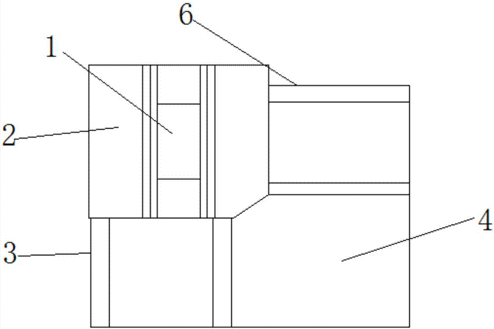
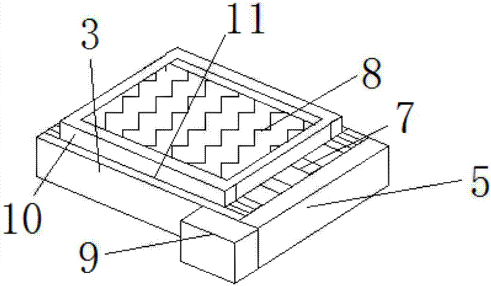
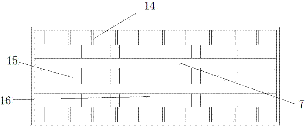
The invention discloses a feeding device of a laser cutting machine, which comprises a main body of a laser machine, a first conveying frame and a second conveying frame. The conveyor frames are respectively installed on both sides of the main body of the laser machine, the positions of the first conveyor frame and the second conveyor frame are perpendicular to each other, and the front ends of the first conveyor frame and the second conveyor frame are fixedly installed with a feeding platform, and Both sides of the first conveyor frame and the second conveyor frame are fixedly equipped with guide frames, the inner cavity of the guide frame is equipped with a conveying guide rail, and the outer side of the guide frame is fixedly equipped with a drive motor, and the drive motor and the conveyor guide rail are fixedly installed. Rotationally connected, the inner side of the guide frame is fixedly installed with a support frame, and the upper ends of the first conveying frame and the second conveying frame are both provided with feeding carts. The feeding device of the laser cutting machine has a reasonable design, is convenient to use, has more practical value, and has a promoting effect on production safety and production efficiency.

Description

technical field [0001] The invention relates to the technical field of mechanical processing, in particular to a feeding device of a laser cutting machine. Background technique [0002] Laser cutting is to focus the laser emitted from the laser into a high power density laser beam through the optical path system. The laser beam irradiates the surface of the workpiece to make the workpiece reach the melting point or boiling point, and at the same time, the high-pressure gas coaxial with the beam blows away the molten or vaporized metal. With the movement of the relative position of the beam and the workpiece, the material will eventually form a slit, so as to achieve the purpose of cutting. [0003] The feeding devices in the existing laser cutting machines are all equipped with two sets of vertically symmetrical guide rails in the same direction, and at the same time, a feeding cart is installed on the guide rails to complete the feeding from the outside to the inside of th...

Claims


Application Information

Patent Timeline
Patent Type & Authority Applications(China)
IPC IPC(8): B23K26/70B23K26/38
CPCB23K26/702B23K26/38
Inventor 刘爱珍
Owner LIANGXI HAOXING IND DESIGN OFFICE
Why Eureka
Try Eureka