[0047] The specific embodiments of the present invention will be further described below with reference to the accompanying drawings, so as to fully understand and implement the implementation process of how the present invention applies technical means to solve technical problems and achieve technical effects. It should be noted that, as long as there is no conflict, each embodiment of the present invention and each feature of each embodiment can be combined with each other, and the formed technical solutions all fall within the protection scope of the present invention.
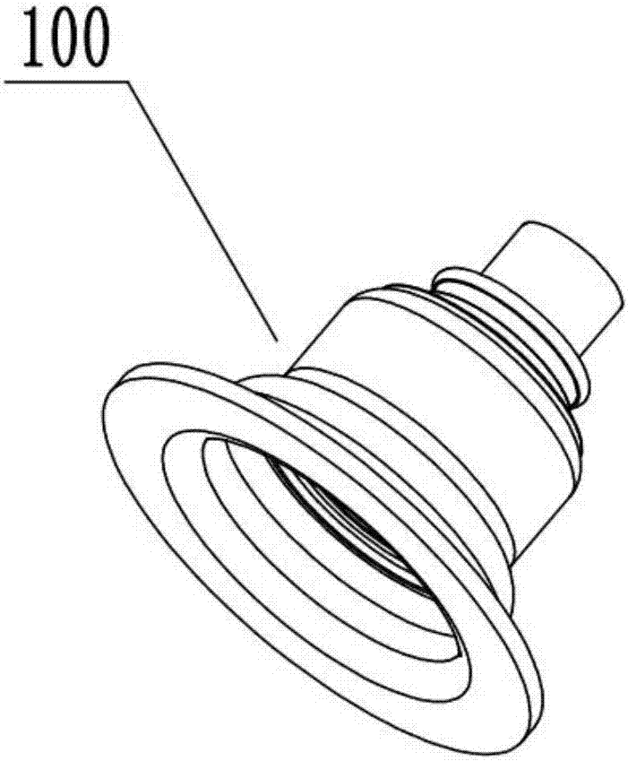
[0048] like figure 1 The product 100 processed by the present invention is a bearing with a sealing ring.
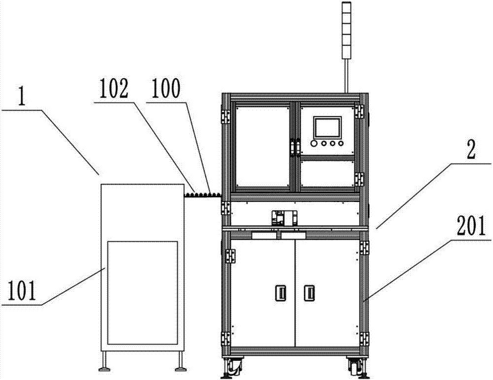
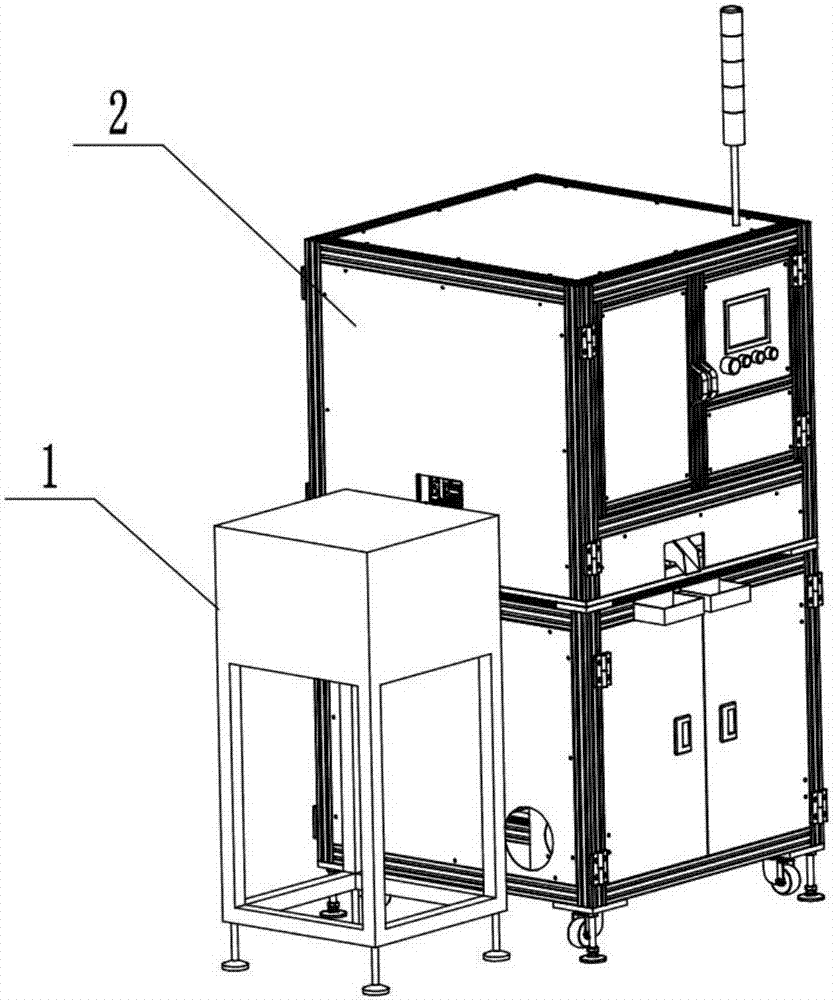
[0049] like Figure 2-Figure 4 As shown, the automatic precision turning machine of this embodiment includes an automatic feeding machine 1, a multi-station turning machine connected to the automatic feeding machine 1, and the control of the automatic feeding machine 1 and the multi-station turning machine. Unit; The automatic feeding machine 1 includes a vibrating feeding device 101 and a linear output channel 102 connected to the discharge end of the vibrating feeding device 101, and the linear output channel 102 extends to the multi-station edger. The vibrating feeding device 101 belongs to the prior art, so the present invention is not described in detail here.
[0050] like Figure 5 to Figure 7 As shown, the multi-station turning machine includes a frame 2, the frame includes a support frame 201 and a bottom support plate 202 fixed in the support frame 201, and a multi-station turntable 203 is installed above the bottom support plate 202 and along the circumferential direction The loading and loading device 3, the pressing detection device 4, the vehicle side device 5, the CCD detection device 6, the qualified product sorting device 7 and the vacancy detection device 8 are sequentially arranged around the multi-station turntable 203. The turntable driving device 9 on the rack 2 is driven, and the peripheral edge of the multi-station turntable 203 is evenly spaced with product fixing bases 204, and the fixing bases 204 are used to support and fix the product (bearing).
[0051] like Figure 8 to Figure 11 As shown, the loading and loading device 3 includes a feeding device 31 and a clamping and loading device 32. The feeding device 31 includes a T-shaped feeding platform 311 fixed above the bottom support plate 202, and a centering detection device installed on one side of the T-shaped feeding platform 311. The device 312 and the pushing device 313 installed at the end of the T-shaped feeding platform 311, the T-shaped feeding platform 311 is installed on the bottom support plate 202 through the support column 314, and the height can be adjusted; On the support plate 202, and the height can be adjusted, the T-shaped feeding platform 311 includes a feeding guide 3111 connected with the linear output flow channel 102 and a feeding table 3112 perpendicular to the feeding guide 3111, and the feeding guide 3111 and the feeding table 3112 have communication The centering detection device 312 includes a fixed rod 3121 fixed on the bottom support plate 202, an adjustment rod 3123 connected with the fixed rod 3121 through the lifting adjustment block 3122, and a U fixed on the adjustment rod 3123. The opening of the U-shaped detection rod 3124 is placed horizontally, the end of the U-shaped detection rod 3124 is installed with a centering photoelectric sensor 3125, and the feeding table 3112 has a through hole through the upper and lower sides. In the U-shaped groove of the rod 3124; the pushing device 313 includes a pushing cylinder 3131 installed on the feeding table 3112, the pushing direction is perpendicular to the feeding guide rail 3111, and a pushing head 3132 fixed at the end of the piston rod of the pushing cylinder 3131; The clamping and loading device 32 includes a loading support frame 321 installed on one side of the T-shaped feeding platform 311 , a horizontal moving loading cylinder 322 fixed on the upper end of the loading support frame 321 and a vertical moving loading cylinder 323 driven by the horizontal moving loading cylinder 322. A loading chuck 324 is mounted on the lower end of the piston rod of the vertically moving loading cylinder 323 . The loading chuck 324 is a pneumatic chuck, that is, the product is clamped by a cylinder driven gripper.
[0052] When the feeding and loading device 3 is working, the product (bearing) conveyed from the automatic feeding machine 1 is conveyed to the receiving guide rail 3111, and continues to be conveyed forward. When the product is placed on the feeding table 3112, it passes through the centering detection device 312. The centering photoelectric sensor 3125 detects whether the product moves in place. Since the center of the product has a through hole, when the signal sent by the transmitting end of the centering photoelectric sensor 3125 is received by its receiving end, it indicates that the product has moved in place, and the signal is sent to the control Unit, the control unit activates the pushing cylinder 3131, which pushes the product towards the clamping and loading device 32, and after being pushed in place, the horizontally moving loading cylinder 322 drives the vertically moving loading cylinder 323 to move towards the product, and the vertically moving loading cylinder 323 Push the loading chuck 324 to approach the product, and the loading chuck 324 picks up the product. After the product is picked up, the loading cylinder 323 moves vertically and the loading cylinder 322 moves horizontally to return to move the product to just above the fixed seat 204. Vertically moving the loading cylinder 323 and the loading chuck 324 act to place the product on the fixed seat 204 .
[0053] like Figure 12 As shown, the compression detection device 4 includes a compression support column 41 fixed on the bottom support plate 202, a vertical compression cylinder 43 fixed on the upper end side of the compression support column 41 through a sliding adjustment block 42, and the vertical compression The pressing column 44 driven by the air cylinder 43 and the detection component 45 installed on the upper end of the pressing column 44, the lower end of the pressing column 44 is fixedly connected with a pressing head 46, and the upper end of the pressing column 44 is axially slidably installed with a pressing sleeve 47 , between the lower end of the compression sleeve 47 and the compression head 46 is installed a spring 48 sleeved on the compression column 44, the compression sleeve 47 is fixedly connected to the end of the piston rod of the vertical compression cylinder 43 through the fixing block 49 The compression detection assembly 45 includes a compression detection photoelectric switch 452 that is fixedly connected with the upper end of the compression sleeve 47 through the fixed bracket 451, and the upper end of the compression column 44 extends out of the compression sleeve 47 and is fixedly installed with a compression detection head 453, The pressing detection head 453 is placed in the detection gap of the pressing detection photoelectric switch 452 .
[0054] When in use, when the product is rotated to the pressing station through the multi-station turntable 203, the vertical pressing cylinder 43 acts to drive the pressing sleeve 47 and the pressing detection photoelectric switch 452 fixed on the upper end of the pressing sleeve 47 to move downward, Due to the action of the spring 48, the pressing head 46 moves toward the product and presses against the product, and the vertical pressing cylinder 3 continues to drive. After moving for a certain distance, when there is a product on the fixing seat 204, the pressing head 46 presses against the product. , and the product is pressed and fixed on the fixing seat 204, the spring 48 is compressed, and the pressing column 44 extends more from the upper end of the pressing sleeve 47 until it is detected by the pressing detection photoelectric switch 452, indicating that the pressing is in place and the detection To the holder 204 there is a product.
[0055] like Figures 13 to 15 As shown, the turning device 5 includes a turning tool control device 51 and a turning waste collection box 52 installed on one side of the multi-station turntable 203. The turning tool control device 51 includes a turning tool support frame 511, which is fixed to the turning tool support frame The vertical control cylinder 512 at the upper end of 511, the horizontal control cylinder 513 driven by the vertical control cylinder 512, and the tool distance control cylinder 514 driven by the horizontal control cylinder 513, the cylinder body of the tool distance control cylinder 514 is connected to the horizontal cylinder through the indexing plate 515. The control cylinder 513 is connected, and the tool 516 is installed at the end of the piston rod of the tool distance control cylinder 514; the bottom support plate 202 of the turning station of the turning device 5 is fixedly installed with a turning tool driving device that drives the rotation of the fixed seat 204 517. The turning tool driving device 517 includes a turning tool driving motor 5171 fixed under the bottom support plate 202, a disk connector 5172 located above the bottom support plate 202 and connected with the output shaft of the turning tool driving motor 5171; when the multi-station turntable 203 rotates When arriving at the turning tool station, the lower end of the fixed seat 204 is connected to the turning tool driving motor 5171 through the magnetic disk connector 5172 .
[0056] When the turning device 5 is working, the turning tool driving motor 5171 drives the product to rotate at a high speed, and the control unit controls the vertical control cylinder 512, the horizontal control cylinder 513 and the tool distance control cylinder 514 of the turning device 5 to act, so that the tool 516 contacts the edge of the product , to achieve the car side.
[0057] like Figure 16 As shown, the CCD detection device 6 includes a CCD detection frame 61 and a CCD 62 fixed on the upper end of the CCD detection frame 61 . Use CCD62 to carry out imaging comparison detection of products, and record the qualified and unqualified information of products.
[0058] like Figure 17 to Figure 22 As shown, the qualified product sorting device 7 includes a product sorting channel 71 and a sorting control device 72 installed on the bottom support plate 202. The product sorting channel 71 is installed on the bottom support plate 202 through the moving device 73, including adjacent The qualified product channel 711 and the defective product channel 712 are respectively set to lead to the qualified product box 74 and the defective product box 75. The defective product box 75 is placed on the release support device 76 of the bottom support plate 202, and the lower part of the release support device 76 is installed. There is a defective product storage device 77 with a defective product box 75 ; the control unit controls the moving position of the product sorting channel 71 and the open and closed state of the release support device 76 according to the detection result of the CCD detection device 6 . The sorting control device 72 includes a sorting support frame 721 located on one side of the multi-station turntable 203 and mounted on the bottom support plate 202, a sorting horizontal pushing cylinder 722 fixed on the upper end of the sorting support frame 721, and the sorting horizontal pushing cylinder 722 is pushed by the sorting horizontally. The sorting vertical push cylinder 723 driven by the cylinder 722 and the sorting chuck 724 driven by the sorting vertical push cylinder 723.
[0059] like Figure 21 , Figure 22 As shown, the release support device 76 includes a support plate 762, one end of which is hinged to the installation groove of the bottom support plate 202 through a hinge shaft 761, and a support plate 762 installed on the lower surface of the bottom support plate 202 for connecting the support plate 762 to the bottom support plate 202. The interlocking electromagnet switch 763; the defective material storage device 77 includes an inclined guide plate 771 installed obliquely below the support plate 762, and a storage box 772 installed at the lower end of the inclined guide plate 771; the inclined guide plate 771 is provided with a through groove near the upper end 7711 and fixed with a compression spring 773 located below the through groove 7711, the compression spring 773 is connected with the support plate 762; the hinge shaft 761 is installed with a torsion spring 764.
[0060]The working process of the qualified product sorting device 7 is as follows: the control unit controls the position of the product sorting channel 71 through the moving device 73 according to the detection signal of the CCD detection device 6. When the qualified product is detected, the qualified product channel 711 is in a working state. , the sorting control device 72 clamps the product and releases it into the qualified product channel 711 and finally outputs it to the qualified product box 74; when the defective product is detected, the mobile device 73 controls the defective product channel 712 to be in a working state, sorting The control device 72 clamps the product and releases it into the defective product channel 711 and finally outputs it to the defective product box 75; the control unit records the number of defective products in the defective product box 75, and when the number reaches to fill the defective product box 75, A signal is given to turn on the electromagnet switch 763, the electromagnet switch 763 is turned on, under the gravity of the defective box 75, the support plate 762 swings downward, and the defective box 75 slides down to the storage box 772 through the inclined guide plate 771 for output ; Under the action of the compression spring 772 and the torsion spring 764, the inclined guide plate 771 returns to its original state, and the electromagnet switch 763 locks it with the bottom support plate 202, waiting for the next command.
[0061] like Figure 23 As shown, the vacancy detection device 8 includes a vacancy detection support frame 81 , a vacancy detection support arm 82 installed on the upper end of the vacancy detection support frame 81 , and a vacancy detection photoelectric sensor 83 installed on the end of the vacancy detection support arm 82 . The vacancy detection device 8 is used to detect whether there is a product on the fixed seat 204, and send the detected signal to the control unit. Only when it is detected that there is no product on the fixed seat 204, the loading and loading device 3 will put the new product on the side of the car. Loaded on the holder 204 .
[0062] like Figure 24 , Figure 25 As shown, the turntable drive device 9 includes a turntable drive motor 91 and a reduction gear 92 respectively fixed below and above the bottom support plate 202. The output shaft of the turntable drive motor 91 is synchronously connected with the input shaft of the reduction gear 92 through a belt 93. The reduction gear The output shaft of 92 is fixedly connected with the center of the multi-station turntable 203 . The control unit controls the rotation of the multi-station turntable 203 according to the set time interval and the signals detected by each sensor, so as to switch the processing stations.
[0063] The trimming machine of the present invention can also be used for trimming other metal parts, such as other metal stamping parts.
[0064] The above-mentioned embodiments are preferred embodiments of the present invention, and are only used to facilitate the description of the present invention, and are not intended to limit the present invention in any form. Within the scope of the technical features of the present invention, equivalent embodiments with partial changes or modifications made by using the technical content disclosed in the present invention, and without departing from the technical features of the present invention, still belong to the scope of the technical features of the present invention.