Constructional engineering concrete mixing conveyor

A technology of construction engineering and concrete, which is applied in mixing plants, cement mixing devices, mixing operation control, etc., can solve problems such as difficult work, low work efficiency, and influence on project progress, so as to ensure the environment, improve work efficiency, and reduce work steps Effect

Active Publication Date: 2017-11-28
上海汇辽科技发展股份有限公司
View PDF9 Cites 0 Cited by
  • Summary
  • Abstract
  • Description
  • Claims
  • Application Information

AI Technical Summary

Problems solved by technology

[0002] In the existing concrete transportation, the method of manually conveying concrete is generally used. In the process of transportation, it needs to consume a lot of manpower to cooperate, resulting in cumbersome construction and low work efficiency. Therefore, in order to improve work efficiency, transportation devices have been used. To replace human transportation, but there are many problems. First, when the concrete enters the hopper, it will be mixed with a lot of concrete that does not meet the requirements, which will bring difficulties to the later work; Backlog; Finally, the transportation pipeline is not easy to clean, long-term accumulation, easy to cause blockage; the existing concrete conveying devices are not movable, due to the large volume of the conveying device, it is very inconvenient to move the conveying device, because the work needs It takes manpower and material resources to move, which brings inconvenience to the construction. After the concrete is prepared, it needs to be guided and transported from the tank truck or concrete mixer to the paving box on the construction site. The specific construction location is constantly changing, which requires that wherever the paving box is laid, the concrete must be delivered. In the prior art, the concrete delivery device is relatively clumsy, and the position and angle of the delivery device cannot be adjusted in real time according to the construction location, which greatly affects Construction efficiency affects project progress

Method used


Image

  • Constructional engineering concrete mixing conveyor
  • Constructional engineering concrete mixing conveyor
  • Constructional engineering concrete mixing conveyor

Examples


Embodiment Construction

[0024] The following will clearly and completely describe the technical solutions in the embodiments of the present invention with reference to the accompanying drawings in the embodiments of the present invention. Obviously, the described embodiments are only some, not all, embodiments of the present invention. Based on the embodiments of the present invention, all other embodiments obtained by persons of ordinary skill in the art without making creative efforts belong to the protection scope of the present invention.

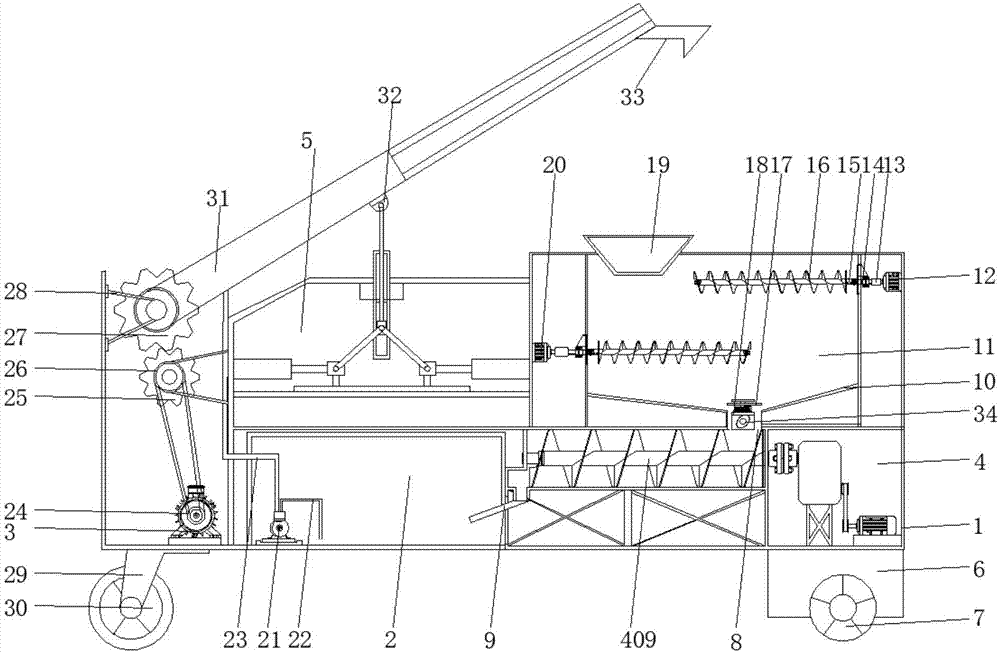
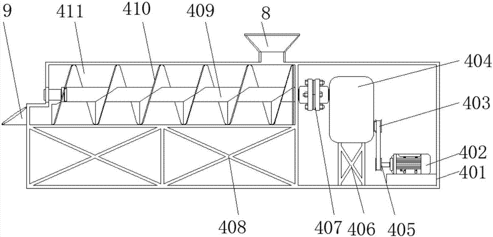
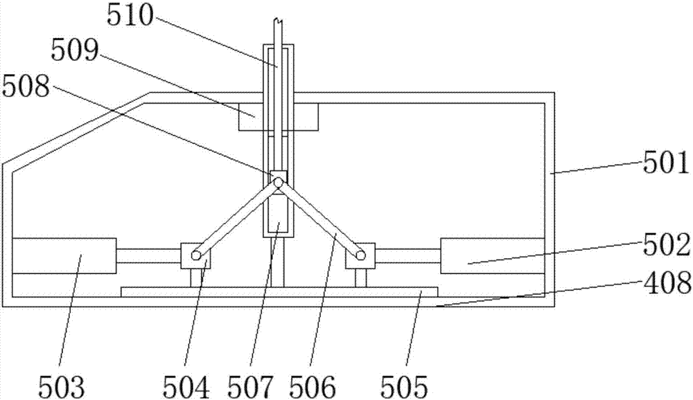
[0025] see Figure 1-4, the present invention provides a technical solution: a concrete mixing conveyor for construction engineering, comprising a box body 1, a transmission device 4 is fixedly connected to the bottom side of the inner wall of the box body 1, and a mixing box 11 is fixedly connected to the top of the outer wall of the transmission device 4. Both sides of the inner cavity of the box 11 are provided with partitions, and the two sides of the inne...


PUM


Abstract

The invention discloses a constructional engineering concrete mixing conveyor which comprises a box. A conveying device is fixedly connected to one side of the bottom of the inner wall of the box, a mixing box is fixedly connected to the top of the outer wall of the conveying device, separating plates are arranged on the two sides of an inner cavity of the mixing box, a first motor and a second motor are fixedly connected to the two sides of the inner wall of the mixing box, output shafts of the first motor and the second motor are rotationally connected with connectors through couplers, and the ends, far away from the couplers, of the connectors are fixedly connected with mixing rotation shafts through flat keys. The constructional engineering concrete mixing conveyor relates to the technical field of conveying equipment. By means of the constructional engineering concrete mixing conveyor, concrete can be stably mixed and conveyed, the work efficiency on a construction site is improved, the number of working steps is decreased, limitation of the environment to concrete transportation and machine overall movement work is reduced, adaptability to the working environment is improved, and the working amount of workers is reduced.

Description

technical field [0001] The invention relates to the technical field of conveying equipment, in particular to a concrete mixing conveyor for construction engineering. Background technique [0002] In the existing concrete transportation, the method of manually conveying concrete is generally used. In the process of transportation, it needs to consume a lot of manpower to cooperate, resulting in cumbersome construction and low work efficiency. Therefore, in order to improve work efficiency, transportation devices have been used. To replace human transportation, but there are many problems. First, when the concrete enters the hopper, it will be mixed with a lot of concrete that does not meet the requirements, which will bring difficulties to the later work; Backlog; Finally, the transportation pipeline is not easy to clean, long-term accumulation, easy to cause blockage; the existing concrete conveying devices are not movable, due to the large volume of the conveying device, it...

Claims


Application Information

Patent Timeline
Patent Type & Authority Applications(China)
IPC IPC(8): B28C5/14B28C7/16B28C9/04
CPCB28C5/14B28C7/163B28C7/167B28C9/04
Inventor 杨小春
Owner 上海汇辽科技发展股份有限公司
Why Eureka
Try Eureka