Portable subway vehicle weighing device
A vehicle weighing and portable technology, which is applied in the direction of measuring devices, weighing, instruments, etc., can solve the problems of high technical work intensity, low measurement accuracy, and large volume, and achieve shortened weighing time, convenient movement, and small volume Effect
- Summary
- Abstract
- Description
- Claims
- Application Information
AI Technical Summary
Problems solved by technology
Method used
Image
Examples
Embodiment 1
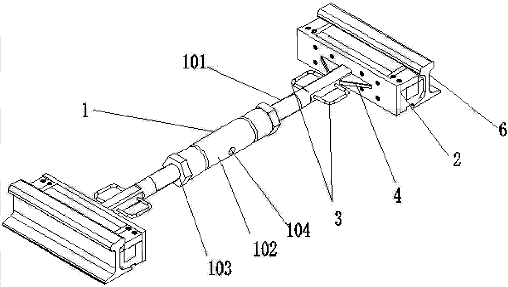
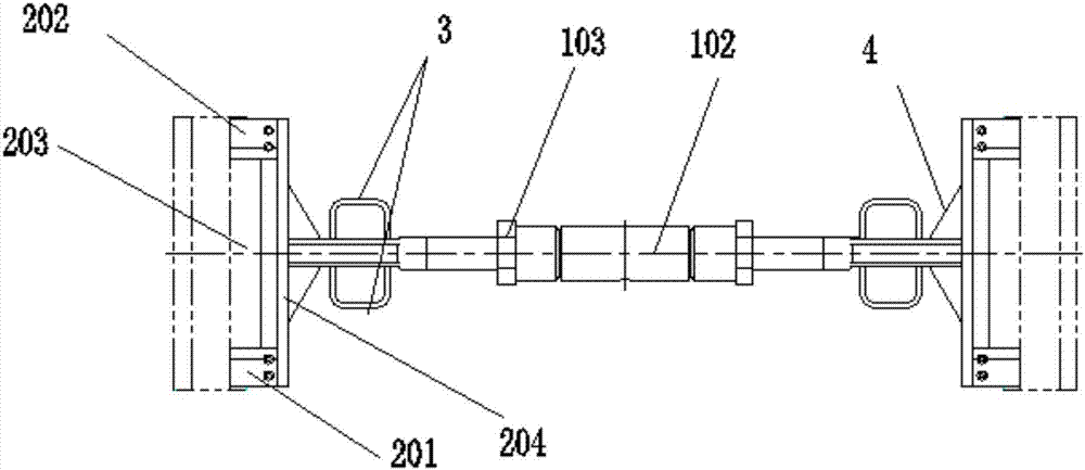
[0032] Such as Figure 1-5 The portable metro vehicle weighing device shown includes a screw adjustment unit 1, a support platform 2 and a sensor 5, the two ends of the screw adjustment unit 1 are fixedly connected to the two support platforms 2, and the sensor 5 is fixed Set inside the support table 2; the lead screw adjustment unit 1 includes a lead screw 101, a lead screw sleeve 102, a lock nut 103, and an adjustment through hole 104, and the two lead screws 101 pass through the lock nut 103 The locking nuts 103 and the screw 101 are threadedly connected to the two ends of the lead screw sleeve 102 respectively, and the adjustment through hole 104 is provided in the middle of the screw sleeve 102 .
[0033] In the above technical solution of this embodiment, when weighing the subway vehicle, the support platform 2 of the weighing device is stuck on the inner side of the two rails, and the length of the weighing device is adjusted by the screw adjusting unit 1 , until the s...
Embodiment 2
[0041] Such as Figure 1-5The portable metro vehicle weighing device shown includes a screw adjustment unit 1, a support platform 2 and a sensor 5, the two ends of the screw adjustment unit 1 are fixedly connected to the two support platforms 2, and the sensor 5 is fixed Located inside the support table 2; the support table 2 includes a first wear plate 201, a second wear plate 202, a third wear plate 203, an end plate 204, and a support member 205, and the end plate 204 is connected to the The support member 205 is fixedly connected by bolts, the first wear plate 201 and the third wear plate 203 are fixed on both ends of the upper surface of the support member 205 by bolts, and the second wear plate 202 is clamped on the between the first wear plate 201 and the third wear plate 203 .
[0042] Further, the bottom of the second wear plate 202 is in contact with the upper part of the sensor 5 .
[0043] In the above technical solution of this embodiment, the support member 205...
PUM
 Abstract
Description
Claims
Application Information
 - R&D
- Intellectual Property
- Life Sciences
- Materials
- Tech Scout
- Unparalleled Data Quality
- Higher Quality Content
- 60% Fewer Hallucinations
Browse by: Latest US Patents, China's latest patents, Technical Efficacy Thesaurus, Application Domain, Technology Topic, Popular Technical Reports.
© 2025 PatSnap. All rights reserved.Legal|Privacy policy|Modern Slavery Act Transparency Statement|Sitemap|About US| Contact US: help@patsnap.com


