Display device

A display device and illuminant technology, applied in the direction of lighting devices, identification devices, components of lighting devices, etc., can solve problems such as display brightness decline, improve imaging quality, maintain image brightness and viewing distance, and achieve sufficient image brightness and the effect of viewing distance

Inactive Publication Date: 2017-11-28
YOUNG OPTICS
View PDF0 Cites 2 Cited by
  • Summary
  • Abstract
  • Description
  • Claims
  • Application Information

AI Technical Summary

Problems solved by technology

However, since the light passing through the diffuser plate 104 will be scattered at a larger angle, the overall display brightness will be significantly reduced when viewed from a long distance.

Method used


Image

  • Display device
  • Display device
  • Display device

Examples


Embodiment Construction

[0018] The aforementioned and other technical contents, features and functions of the present invention will be clearly presented in the following detailed description of the embodiments with reference to the drawings. The directional terms mentioned in the following embodiments, such as: up, down, left, right, front or back, etc., are only referring to the directions of the drawings. Accordingly, the directional terms are used to illustrate and not to limit the invention.

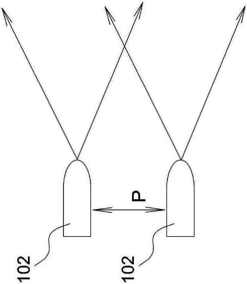
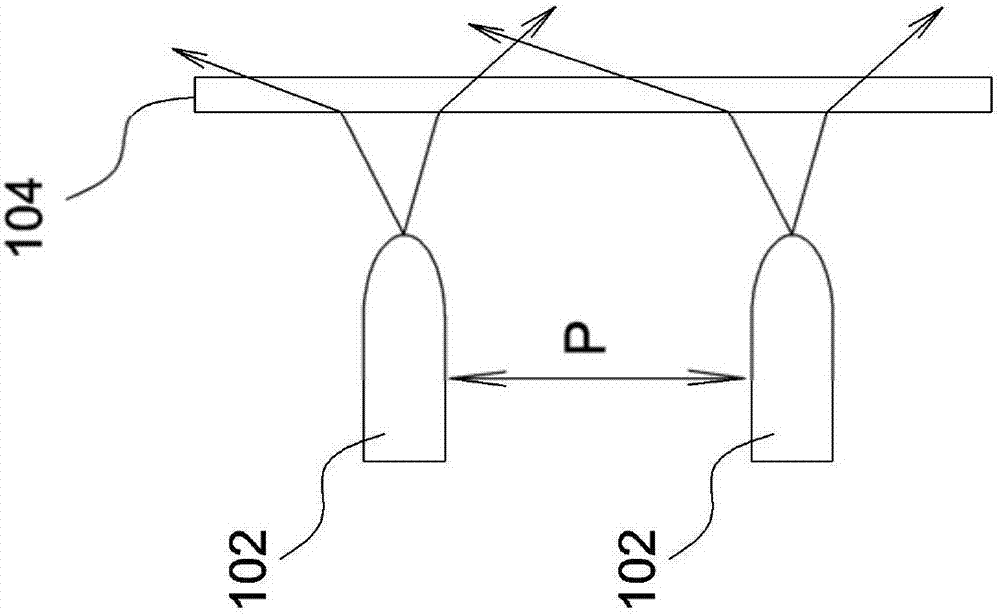
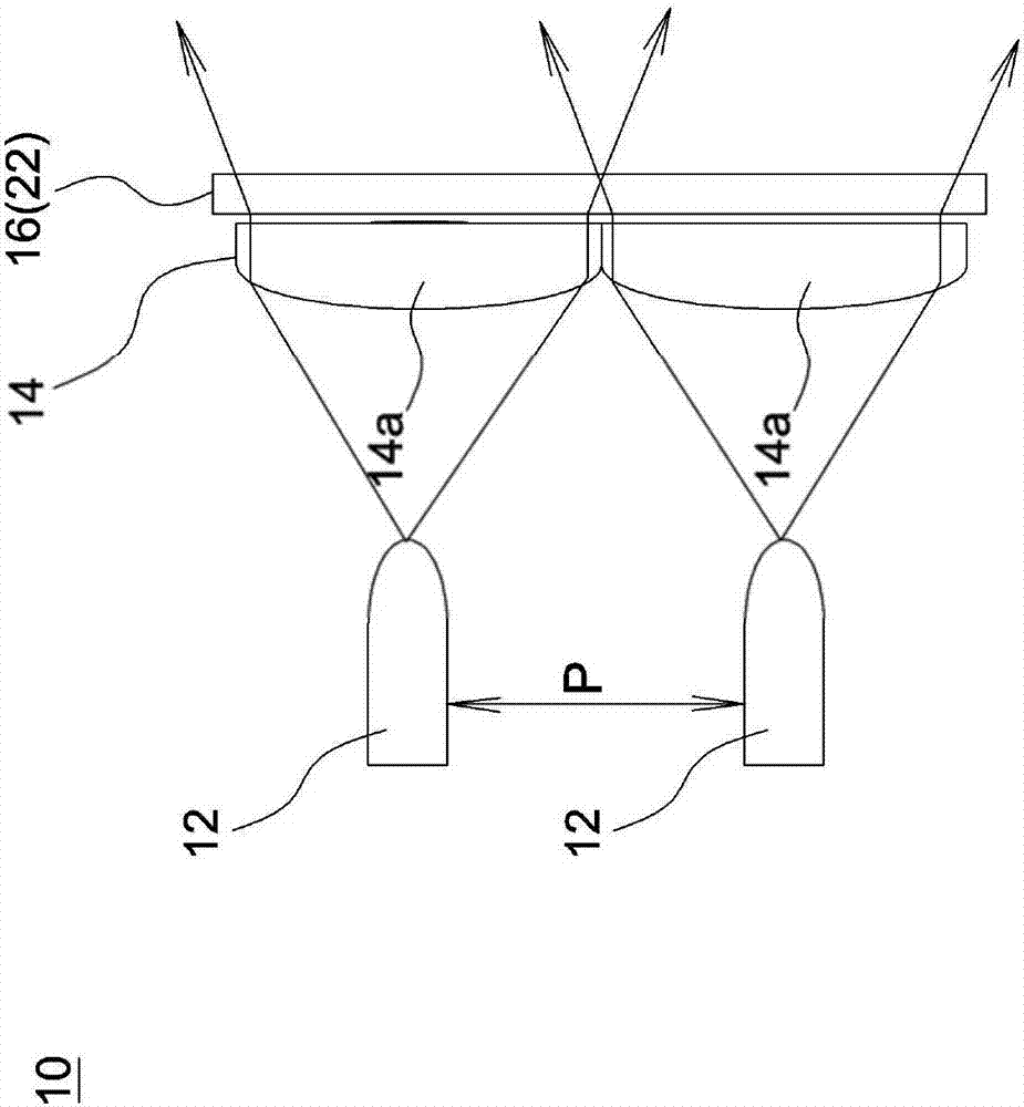
[0019] image 3 It is a schematic diagram of a display device according to an embodiment of the present invention. like image 3 As shown, the display device 10 includes a plurality of point light emitters 12, a lens array 14 and a light diffusing element 16 (such as a diffuser plate 22, a fog structure, a fog surface, fog glass or frosted glass). Two adjacent point luminous bodies 12 have a pitch P, and each point luminous body 12 can be selectively illuminated and extinguished, so in one embodiment, a...


PUM


Abstract

Provided is a display device. The device includes a plurality of point luminophors, a fogging surface body and a lens array. A certain separation distance exists between every two adjacent point luminophors, and the fogging surface body is arranged on the light emitting sides of the point luminophors. The lens array is arranged on one side of the fogging surface body and provided with multiple lens units with positive diopters. Through the match of a light diffusing component and the lens array, after light rays emitted by the luminous point luminophors penetrate through the lens array and the light diffusing component, an image, which is excellent in quality and can be watched from a short distance, can be formed, and the sufficient image luminance and visual range can be maintained at the same time.

Description

technical field [0001] The present invention relates to a display device, and in particular to a display device which utilizes point light emitters to arrange and display information. Background technique [0002] Currently, a display device with an array of point light sources, such as a large-scale LED display board, usually uses a plurality of bright LEDs to arrange characters or patterns to be displayed. However, limited by the bonding pitch and heat dissipation requirements of the LEDs, a certain distance must be maintained between the LEDs constituting each pixel. Therefore, when viewing the display device at a close distance, the image will appear discontinuously dotted, resulting in poor performance. image quality. like figure 1 As shown, since a distance P needs to be maintained between the two light emitting diodes 102 , the image will show discontinuous dot distribution when viewed at a close distance. Therefore, in order to improve the image quality, such as ...

Claims


Application Information

Patent Timeline
Patent Type & Authority Applications(China)
IPC IPC(8): G09F9/33G02B27/09
CPCG02B27/0961G09F9/33F21V5/007F21V13/02
Inventor 徐志鸿陈怡学
Owner YOUNG OPTICS
Why Eureka
Try Eureka