
Near single module quasi gradient refractive rate large mode field gain optical fiber and preparation method

A technology of graded-refractive-index and gain fiber, applied in the field of optics, can solve problems such as difficult single-mode output and limited mode field area, and achieve the effect of improving absorption utilization rate, good utilization rate, and high absorption efficiency

Inactive Publication Date: 2012-08-01
XI'AN INST OF OPTICS & FINE MECHANICS - CHINESE ACAD OF SCI
View PDF5 Cites 12 Cited by
  • Summary
  • Abstract
  • Description
  • Claims
  • Application Information

AI Technical Summary

Problems solved by technology

Fibers with a step-index profile can easily generate single-mode output, but the mode field area is limited and cannot be used to generate high power; fibers with a graded-index profile have a larger mode field area, but it is not easy to generate a single-mode output. Modulo output

Method used


Image

  • Near single module quasi gradient refractive rate large mode field gain optical fiber and preparation method
  • Near single module quasi gradient refractive rate large mode field gain optical fiber and preparation method
  • Near single module quasi gradient refractive rate large mode field gain optical fiber and preparation method

Examples


preparation example Construction

[0045] The preparation method of the near-single-mode quasi-graded-index large-mode-field-gain optical fiber provided by the present invention is: the method comprises the following steps:

[0046] 1) Preparation of rare earth doped fiber core rod:

[0047] 1.1) Using chemical vapor deposition MCVD and solution doping or rare earth chelate vapor deposition, the rare earth compound is evenly mixed into the deposition layer in the quartz tube to form a large mode field quartz optical fiber core layer;

[0048]1.2) The large-mode-field silica fiber core layer obtained in step 1.1) is drawn into several small core rods with uniform diameters by a pre-stretching process, and the small core rods are integrated to form a small core rod group to form a rare earth-doped optical fiber Mandrel;

[0049] 2) Make a non-uniform Bragg cladding casing:

[0050] 2.1) Using chemical vapor deposition MCVD, changing the chemical composition of adjacent deposition layers to form alternating clad...

example 1

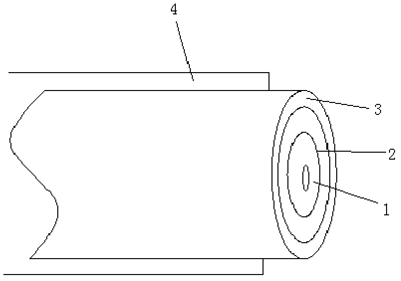
[0068] Example 1: A high-power cladding-pumped near-single-mode quasi-graded-index ytterbium-doped fiber, including a ytterbium-doped silica core 1, a ring gain region 2, a quartz cladding 3 and a low-refractive index coating 4, its structure The feature is that there is a fiber core satisfying the single-mode transmission condition in the cladding layer 3 . A series of loop gain regions 2 are concentrically distributed with the fiber.

example 2

[0069] Example 2: A high-power cladding-pumped near-single-mode quasi-graded-index three-core ytterbium-doped fiber, including three ytterbium-doped silica cores 1, annular gain region 2, silica cladding 3 and low-refractive index coating 4 , the structural feature is: three ytterbium-doped fiber cores with the same structure in the cladding 3 are parallel to each other and arranged symmetrically along the fiber cores, and the distance between the three ytterbium-doped fiber cores 1 is 1-20um. A series of loop gain regions 2 are concentrically distributed with the fiber.

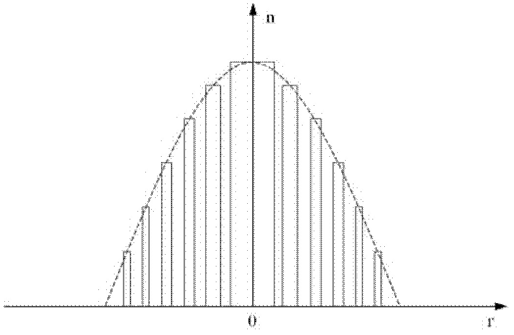
[0070] Both the core 1 and the ring gain region 2 need to meet the single-mode transmission condition of the laser wavelength, according to the mode equation in the fiber:

[0071] Helmholtz equation:

[0072] d 2 Φ dr 2 + 1 r ...


PUM


Abstract

The invention relates to a near single module quasi gradient refractive rate large mode field gain optical fiber and a preparation method. The gain optical fiber comprises a fiber core, a wrapping layer wrapped on the outer portion of the fiber core and an annular gain area arranged between the gain fiber core and the wrapping layer. The near single module quasi gradient refractive rate large mode field gain optical fiber and the preparation method achieves laser output with high light beam quality, is capable of obtaining large mode field area and effectively improves output power of an optical laser device.

Description

technical field [0001] The invention belongs to the field of optics and relates to an optical fiber, in particular to a near-single-mode quasi-gradient refractive index large-mode-field gain optical fiber for high-power optical fiber lasers or amplifiers and a preparation method. Background technique [0002] Due to the characteristics of small size, high efficiency, long life, good beam quality, and maintenance-free, fiber lasers have broad application prospects in advanced manufacturing, national defense security, and scientific research. The development of this new generation of high-power lasers has been It is the focus of attention of the international laser industry. In the field of high-energy fiber lasers, foreign companies are not only far ahead in technology, but also firmly occupy a monopoly position in the market. Many fiber laser research groups in my country have also done a lot of work and achieved some good scientific research results, but most of them are c...

Claims


Application Information

Patent Timeline
IPC IPC(8): G02B6/028G02B6/036C03B37/014C03B37/025
CPCC03B2201/34C03B37/01222C03B2203/26C03B2203/34C03B37/01211
Inventor 段开椋朱永刚林傲祥赵卫
Owner XI'AN INST OF OPTICS & FINE MECHANICS - CHINESE ACAD OF SCI
Learn More