Optical homogenzing device and optical instrument having said light homogenizing device

An optical device, a technology for uniform light, applied in optics, optical components, instruments, etc., can solve problems such as light leakage, and achieve the effect of reducing the divergence angle, improving contrast, and avoiding light leakage.

Inactive Publication Date: 2004-10-20
DELTA ELECTRONICS INC
View PDF0 Cites 13 Cited by
  • Summary
  • Abstract
  • Description
  • Claims
  • Application Information

AI Technical Summary

Problems solved by technology

[0007] Furthermore, even if the relative position between the optical channel and the transmission lens group and the DMD chip can be acc

Method used


Image

  • Optical homogenzing device and optical instrument having said light homogenizing device
  • Optical homogenzing device and optical instrument having said light homogenizing device
  • Optical homogenzing device and optical instrument having said light homogenizing device

Examples


Embodiment Construction

[0045] specific implementation

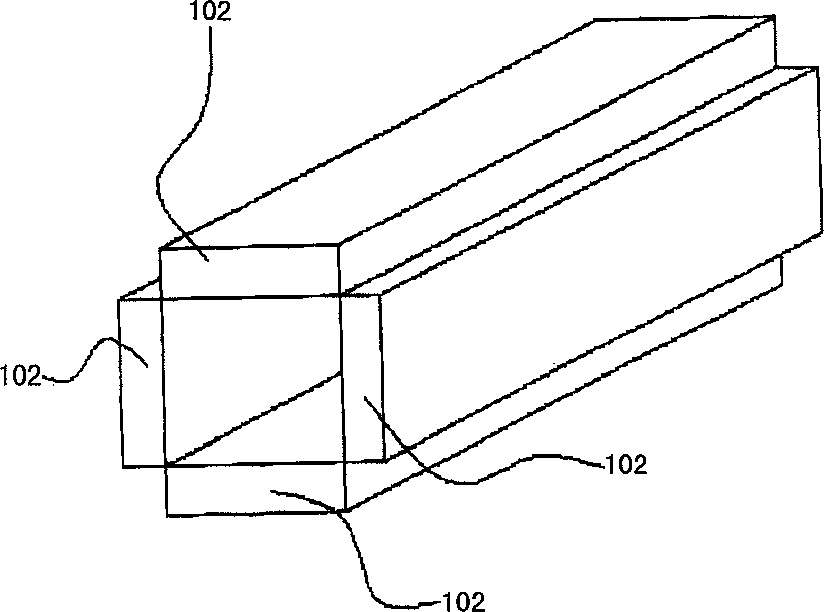
[0046] Figure 4A It is a schematic structural diagram of a light homogenizing device according to a preferred embodiment of the present invention. Figure 4B It is a schematic structural diagram of a light homogenizing device according to another preferred embodiment of the present invention.

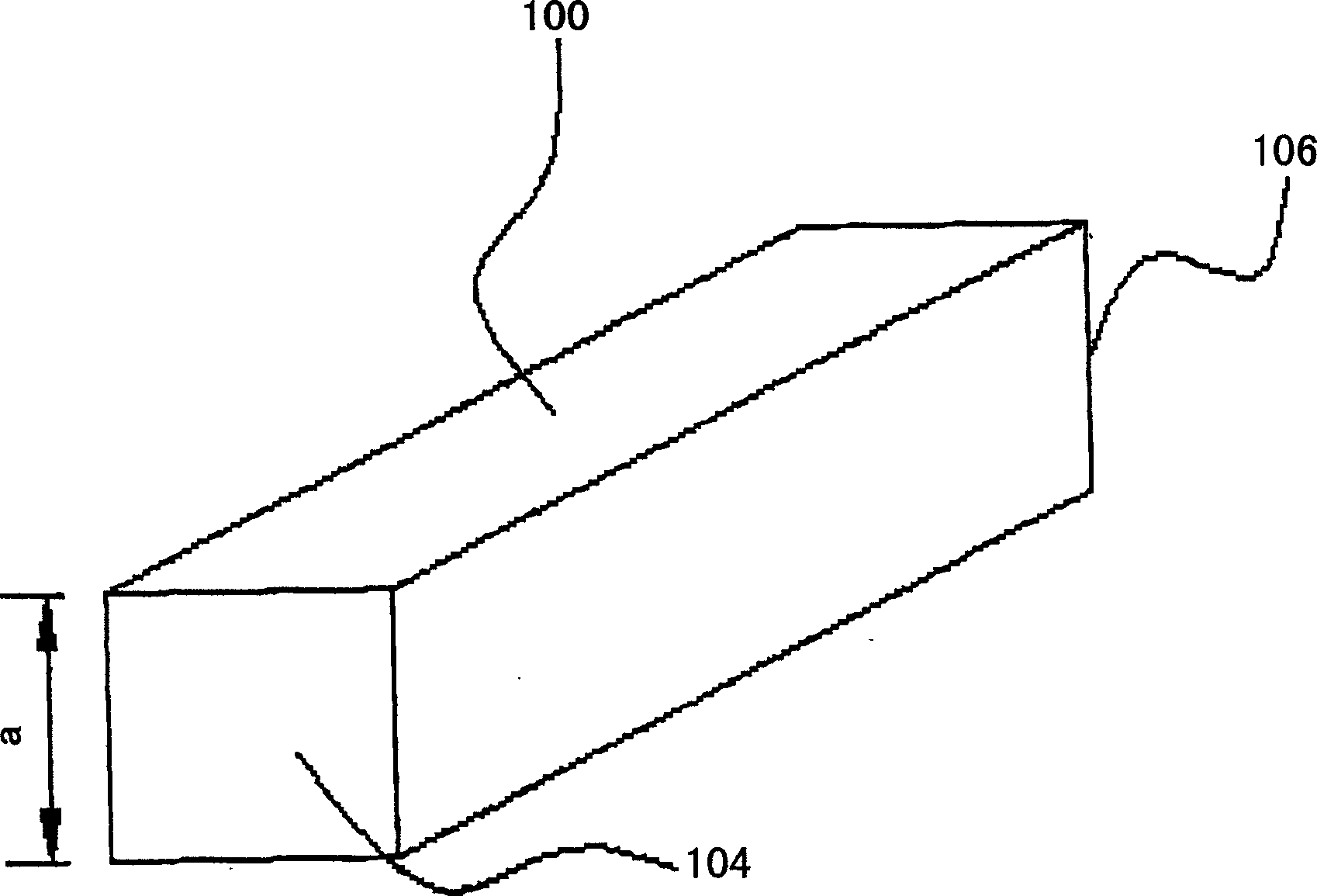
[0047] Please refer to FIG. 4A , the light homogenizing device 200 of the present invention is a wedge-shaped structure, such as a wedge-shaped solid transparent body, and the material of the wedge-shaped structure is, for example, glass. The light homogenizing device 200 has a light incident surface 204 and a light exit surface 206 , and the size or area of ​​the light incident surface 204 is smaller than the size or area of ​​the light exit surface 206 . Furthermore, the shape of the light incident surface 204 is a square, that is, the aspect ratio is 1. The shape of the light emitting surface 206 corresponds to the shape of the active area of ​​th...


PUM


Abstract

An optical homogenizer has a square incident surface and an exit surface with a shape relative to that of active region of optical gate. An optical device with said optical homogenizer positioned between light source and optical gate is also disclosed. Its advantage is high greatly decreased divergence angle for its exit surface.

Description

technical field [0001] The invention relates to a light homogenizing device that receives light and transmits uniform light, in particular relates to a light homogenizing device that receives non-uniform light and transmits uniform light, and can reduce the light divergence angle and has the light homogenization device. The optics of the device. Background technique [0002] Today, the world is moving towards digitalization, and imaging technology is gradually developing towards digitalization along with this trend. Compared with the current display device, the digital display device for processing digital data can accurately reproduce the color of the original image without loss of image, brightness and reliability. Therefore, the importance of digital display devices is also becoming more and more important. [0003] The key technology of the digital display device lies in the digital micro-mirror device (Digital Micro-mirror Device, referred to as DMD), a semiconductor ...

Claims


Application Information

Patent Timeline
IPC IPC(8): G02B5/04G02B26/08G02B27/09
Inventor 张绍雄林益弘
Owner DELTA ELECTRONICS INC
Why Eureka
Try Eureka