
Optical disc driver connector and improvement method for solving problem of floating of optical disc driver connector

A technology for optical disc drives and connectors, which is applied to optical drive connectors and the field of improving the floating height of optical drive connectors. It can solve the problems of upward movement of pins, tilting, ODDConn floating heights, etc., and achieves low design and production costs. simple effect

Inactive Publication Date: 2017-11-28
ZHENGZHOU YUNHAI INFORMATION TECH CO LTD
View PDF6 Cites 0 Cited by
  • Summary
  • Abstract
  • Description
  • Claims
  • Application Information

AI Technical Summary

Problems solved by technology

In the process of use, the Pin is loose in the Pin socket of the PCB, that is, the Pin will move upward from the Pin socket, causing the ODD Conn to appear floating / warping and other bad problems

Method used


Image

  • Optical disc driver connector and improvement method for solving problem of floating of optical disc driver connector
  • Optical disc driver connector and improvement method for solving problem of floating of optical disc driver connector
  • Optical disc driver connector and improvement method for solving problem of floating of optical disc driver connector

Examples


Embodiment 1

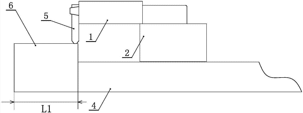
[0036] Embodiment one: if Figure 3 to Figure 5 As shown, the supporting device includes a top cover 5 and a PCB edge 6 arranged on the optical disc drive 1 . The top cover 5 is fixed on the side of the optical disc drive 1 away from the connector 2 and extends downward. The top cover 5 can be made of hard plastic or metal according to needs. In the original design, the width of the PCB side 6 is L, but in the design of the present invention, the width of the PCB side 6 is L1, and L1 is greater than L. That is to say, in this invention, the side 6 of the PCB extends to the side close to the connector 2 to the bottom of the top cover 5 until the bottom of the top cover 5 abuts against the top surface of the side 6 of the PCB. The optical drive connector as a whole is supported, and the central position of the optical drive connector is balanced, so the optical drive connector will not be tilted and floated high. Moreover, the cooperation between the top cover 5 and the edge o...

Embodiment 2

[0038] Embodiment two: if Figure 6 to Figure 8 As shown, the supporting device includes a first fixing block 7 and an adjusting bolt 8 arranged on the optical disc drive 1 . The first fixing block 7 and the adjusting bolt 8 can be made of hard plastic or metal as required. The first fixed block 7 is fixedly arranged on the side of the optical disk drive 1 away from the connector 2. The first fixed block 7 is provided with an internally threaded hole. The adjusting bolt 8 is matched with the internally threaded hole and the head of the adjusting bolt 8 is fixed on the first above the block 7 , the screw part is below the first fixing block 7 and the end of the screw is against the top surface of the PCB 4 . During specific installation, the adjustment bolt 8 can be properly adjusted according to the fixed position of the optical disk drive connector to ensure the support of the adjustment bolt 8 to the optical disk drive connector.

[0039] Similarly, in order to prevent the...

Embodiment 3

[0041] Embodiment three: as Figure 9 As shown, the difference from the second embodiment is that the supporting device also includes a PCB edge 6 . The edge 6 of the PCB extends to the side close to the connector 2 to the bottom of the adjustment bolt 8 , and the bottom end of the screw rod of the adjustment bolt 8 leans against the top surface of the edge 6 of the PCB. In this way, the length of the adjusting bolt 8 can be shortened, and the supporting strength of the adjusting bolt 8 can be enhanced.


PUM


Abstract

The invention discloses an optical disc driver connector and an improvement method for solving the problem of floating of the optical disc driver connector. An optical disc driver is connected with a connector and is attached and fixed to a PCB through a Pin; and a support apparatus for supporting and keeping the bottom surface of the optical disc driver parallel to the top surface of the PCB is arranged between one side, far away from the connector, of the optical disc driver and the PCB. The support apparatus can be adjusted by moving up and down between the bottom surface of the optical disc driver and the top surface of the PCB. The support apparatus for supporting and keeping the bottom surface of the optical disc driver parallel to the top surface of the PCB is arranged between one side, far away from the connector, of the optical disc driver and the PCB, so that the optical disc driver connector is supported, the center of the optical disc driver connector is balanced, and the optical disc driver connector does not tilt and float.

Description

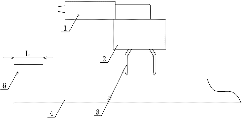
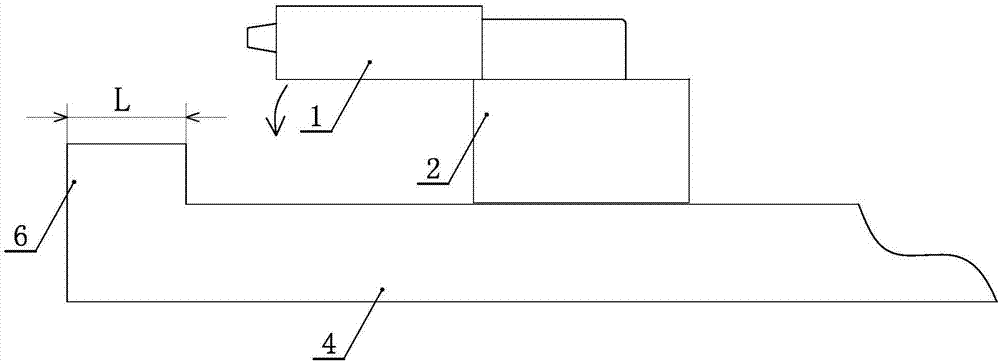
technical field [0001] The invention relates to the technical field of electronic components, in particular to an optical disc drive connector and an improvement method for solving the floating height of the optical disc drive connector. Background technique [0002] At present, the ODD (optical disc drive) Conn (connector) of existing products often has bad problems such as floating height / warping, such as figure 1 with figure 2 As shown, sometimes the defective rate is even as high as 10%. It has been confirmed that the design of the ODD Conn itself is consistent with the previous matching of the PCB. The ODD Conn is mounted and fixed on the PCB (printed circuit board) through the Pin (pin) to achieve the matching between the two, and there is no design problem. . During use, the pins are loose in the pin sockets of the PCB, that is, the pins will move upwards from the pin sockets, resulting in adverse problems such as floating / warping of the ODD Conn. Contents of th...

Claims


Application Information

Patent Timeline
Patent Type & Authority Applications(China)
IPC IPC(8): G11B21/16
CPCG11B21/16
Inventor 张小行
Owner ZHENGZHOU YUNHAI INFORMATION TECH CO LTD
Learn More