
Magnetic stabilization type contactor

A contactor and magnetic stabilization technology, which is applied in the direction of electromagnetic relays, electromagnetic relay details, relays, etc., can solve problems affecting the normal operation of contactors, low electromagnetic utilization rate, and adverse effects of electrical appliances, so as to improve electromagnetic utilization rate, The effect of prolonging the service life and improving product quality

Inactive Publication Date: 2017-11-28
戴丁志
View PDF6 Cites 4 Cited by
  • Summary
  • Abstract
  • Description
  • Claims
  • Application Information

AI Technical Summary

Problems solved by technology

[0003] Contactors are generally composed of electromagnetic components, load components, and housing components, of which: electromagnetic components include moving iron cores, static iron cores, coils (enameled wires), coil formers, magnetic sheets, and cover plates, etc., and housing components include upper cover shells , base, and load components include upper contact piece, lower contact piece, intermediate contact bridge, conductive piece, top column, overtravel spring, etc. The magnetic piece and cover plate wrap the coil and the moving and static iron cores in a half-wrapped manner, resulting in leakage Magnetic phenomenon occurs, the magnetic loss is large, and the electromagnetic utilization rate is low
This affects the normal operation of the contactor and has adverse effects on the electrical appliances it is applied to.

Method used


Image

  • Magnetic stabilization type contactor
  • Magnetic stabilization type contactor
  • Magnetic stabilization type contactor

Examples


Embodiment Construction

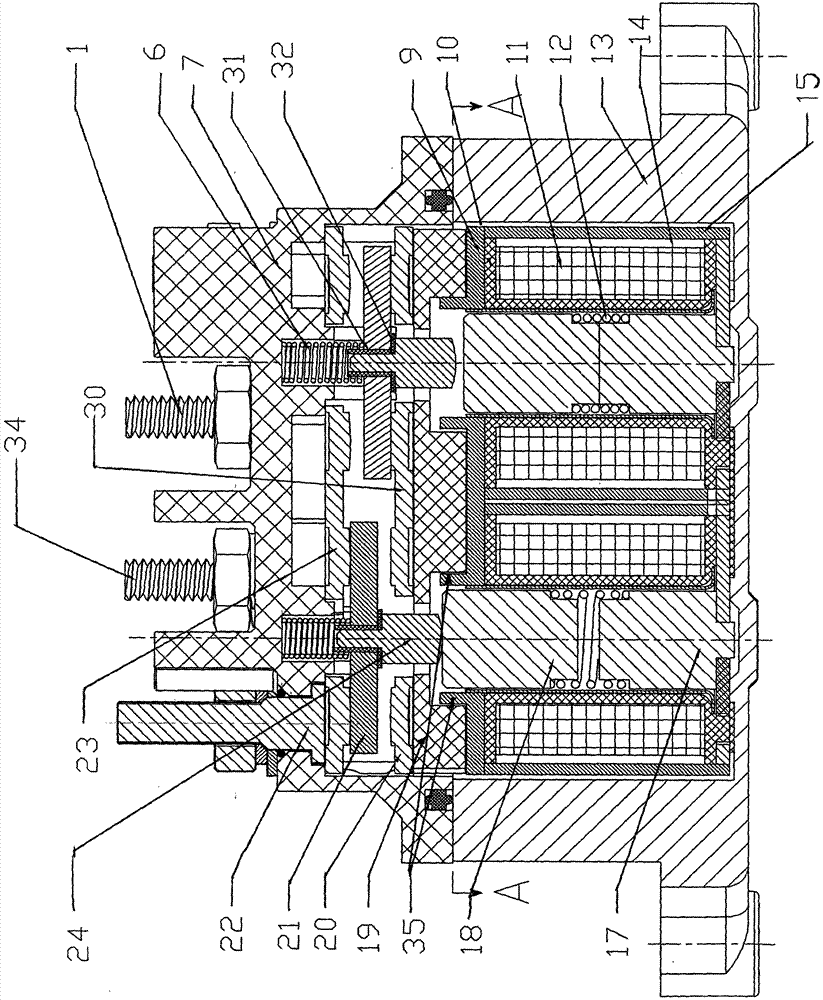
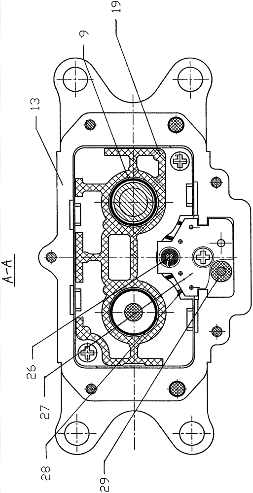
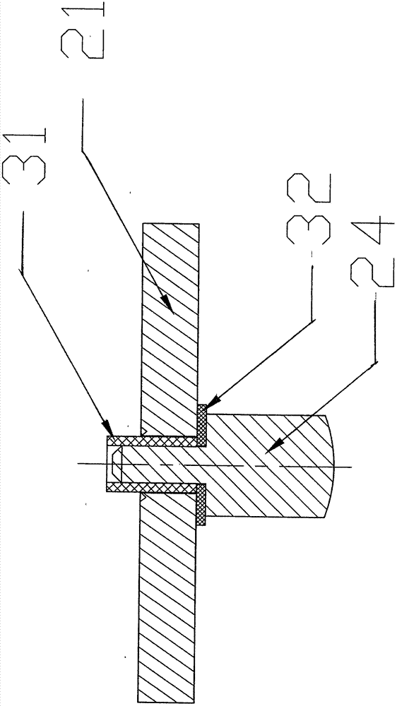
[0012] refer to figure 1 , figure 2 , image 3 It can be seen that the stabilized magnetic contactor of the present invention is composed of electromagnetic components (also known as electromagnetic components), load components, and housing components, wherein the electromagnetic components include a moving iron core 18, a static iron core 17, a coil 11, a coil frame 10, a magnetic The sheet 9 and the cover plate 19, the housing member includes the upper cover shell 7, the base 13, the load member includes the upper contact sheet 30, the lower contact sheet 23, the middle contact bridge 21, the conductive sheet 20, the top post 24, and the overtravel spring 6, The magnetic sheet 9 has a protruding structure 35 (manufactured by a stretching process) connected to the cover plate 19 , and an insulating paper frame 14 and a magnetic yoke 15 are installed between the coil 11 and the inner wall of the base 13 . Between the top post 24 and the middle contact bridge 21, a vertical ...


PUM


Abstract

The invention discloses a magnetic stabilization type contactor. The magnetic stabilization type contactor is composed of an electromagnetic component, a load component and a shell component; the electromagnetic component comprises a moving iron core (18), a fixed iron core (17), a coil (11), a coil frame (10), a magnetic sheet (9) and a cover plate (19); the shell component includes an upper cover housing (7) and a base (13); the load component includes an upper contact sheet (30), a lower contact sheet (32), a middle contact bridge (21), a conductive sheet (20), jacking pillars (24) and over-travel springs (6); the magnetic sheet is provided with a protruding structure (35) which is connected with the cover plate; and an insulating paper holder (14) and a magnetic yoke (15) are mounted between the coil and the inner wall of the base. According to the magnetic stabilization type contactor of the invention, the coil is integrally wrapped with the insulating paper holder, the magnetic yoke and the coil frame; the magnetic sheet with the protruding structure is adopted, and therefore, magnetic leakage amount can be decreased during the operation process of the coil, the moving iron core and the fixed iron core, and magnetic loss can be small, and thus, an electromagnetic utilization rate can be improved, the product quality of the contactor is improved, and the service life of the contactor is prolonged.

Description

technical field [0001] The invention relates to a contactor for commutation or on-off control of electric current. Background technique [0002] A contactor (belonging to a relay) is an electrical product equipped to control the power supply to the line, reversing the current, or controlling on-off. It is widely used in household appliances and industrial products. In recent years, with the development of electric vehicles (such as hybrid vehicles, fuel cell vehicles, etc.), contactors are being used as their power switches. [0003] Contactors are generally composed of electromagnetic components, load components, and housing components, of which: electromagnetic components include moving iron cores, static iron cores, coils (enameled wires), coil formers, magnetic sheets, and cover plates, etc., and housing components include upper cover shells , base, and load components include upper contact piece, lower contact piece, intermediate contact bridge, conductive piece, top c...

Claims


Application Information

Patent Timeline
IPC IPC(8): H01H50/44H01H50/16
CPCH01H50/44H01H50/16
Inventor 戴丁志
Owner 戴丁志
Learn More