Pole-following rotor of rotary motor

A rotating electrical machine, cis-pole technology, applied in the direction of magnetic circuit rotating parts, magnetic circuit shape/style/structure, etc., can solve the problems of low utilization rate of permanent magnets, affecting rotor application, increasing motor output, etc. The effect of low utilization rate, reduction of magnetic flux leakage of magnets, and reduction of production costs

Inactive Publication Date: 2012-07-11
MIDEA WELLING MOTOR TECH SHANGHAI
View PDF5 Cites 4 Cited by
  • Summary
  • Abstract
  • Description
  • Claims
  • Application Information

AI Technical Summary

Problems solved by technology

[0002] In the prior art, the magnetic flux of each pole of the circumferentially magnetized embedded permanent magnet motor is provided by two permanent magnets connected in parallel, which effectively increases the magnetic flux density in the air gap between the stator and the rotor, thereby increasing the output of the motor, such as figure 1 As shown; however, the utilization rate of the permanent magnet at the bottom is low, and the magnetic flux leakage is abundant, and the rotating shaft often requires stainless steel, or uses a magnetically isolated copper sleeve, such as figure 2 As shown, the cost is very high, which affects the application of this structure rotor

Method used


Image

  • Pole-following rotor of rotary motor
  • Pole-following rotor of rotary motor
  • Pole-following rotor of rotary motor

Examples


no. 1 example

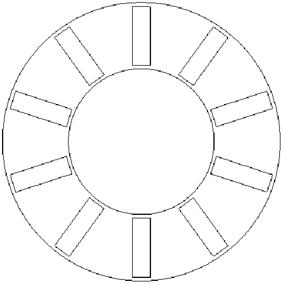
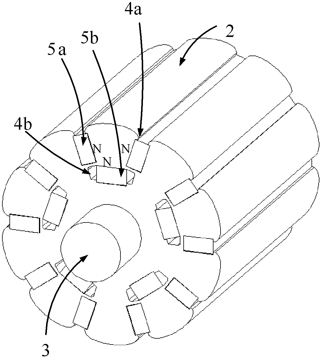
[0016] see image 3 The cis-polar rotor of this rotating electrical machine includes a rotor composed of a rotating shaft 3 and a laminated iron core 2. The laminated iron core 2 is provided with several first permanent magnets that rotate along the axis of the rotating shaft 3 and are magnetized in the circumferential direction of the rotor relative to the axis. The magnetic pole part 5a is also provided with several second permanent magnetic pole parts 5b that rotate along the axis of the rotating shaft 3 and are magnetized in the radial direction of the rotor relative to the axis in the laminated core 2. The number of the second permanent magnetic pole parts 5b is the first 1 / 2 of the number of permanent magnet pole parts 5a.

[0017] In this embodiment, the rotor is a 10-pole rotor, and there are 10 first permanent magnetic pole parts 5a in total. The polarities of each adjacent group of first permanent magnetic pole parts 5a are opposite, and the polarities of the second ...

no. 2 example

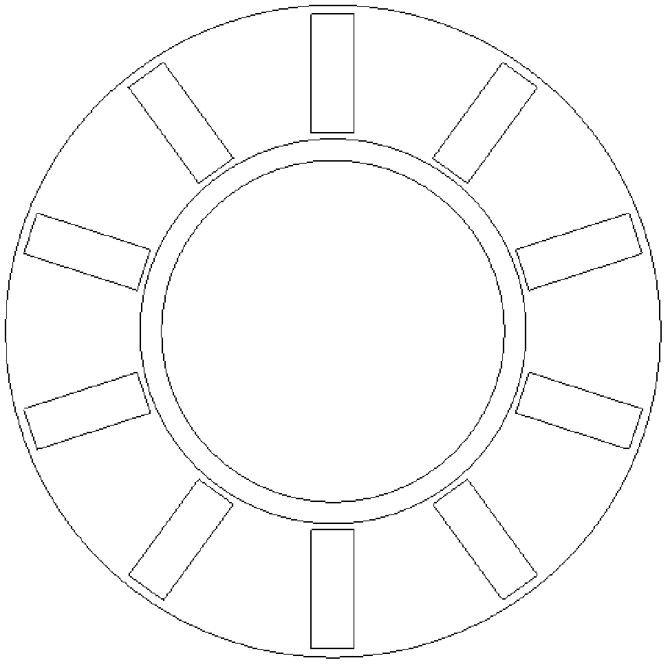
[0020] see Figure 4 , The main difference between the parallel pole rotor of this rotating electrical machine and the first embodiment is that the second permanent magnet groove (no label in the figure) is equivalent to the second permanent magnet pole part 5b, and there is no gap. Other unmentioned parts are the same as the first embodiment and will not be repeated.

no. 3 example

[0022] see Figure 5 The main difference between the parallel pole rotor of this rotating electrical machine and the first embodiment is that the second permanent magnet pole part 5b is embedded in the outer layer of the laminated core 2 through the second permanent magnet slot 4b, that is, the first permanent magnet pole part 5 a is embedded in the inner layer of the laminated core 2 . Other unmentioned parts are the same as the first embodiment and will not be repeated.


PUM


Abstract

A pole-following rotor of a rotary motor comprises a rotor consisting of a rotating shaft and a laminated core, wherein a plurality of first permanent magnet pole pieces rotating along the axis of the rotating shaft and magnetized in the circumferential direction of the rotor relative to the axis are arranged in the laminated core; a plurality of second permanent magnet pole pieces rotating along the axis of the rotating shaft and magnetized in the radial direction of the rotor relative to the axis are also arranged in the laminated core; the quantity of the second permanent magnet pole pieces is half of that of the first permanent magnet pole pieces; the polarities of the adjacent first permanent magnet pole pieces are opposite, and the polarities of the second permanent magnet pole pieces are the same; the polarity of the second permanent magnet pole pieces is the same as the opposite polarity of the rotor; and the first permanent magnet pole pieces are embedded into the laminated core through first permanent magnet slots, and the second permanent magnet pole pieces are embedded into the laminated core through second permanent magnet slots. The pole-following rotor provided by the invention has a simple and reasonable structure, reduces magnetic leakage of a magnet, improves the utilization ratio of the magnet, solves the problem that the rotating shaft has to be made of stainless steel or a magnetism isolating copper sleeve, and has effectively reduced production cost.

Description

technical field [0001] The invention relates to a rotating electrical machine, in particular to a forward pole rotor of the rotating electrical machine. Background technique [0002] In the prior art, the magnetic flux of each pole of the circumferentially magnetized embedded permanent magnet motor is provided by two permanent magnets connected in parallel, which effectively increases the magnetic flux density in the air gap between the stator and the rotor, thereby increasing the output of the motor, such as figure 1 As shown; however, the utilization rate of the permanent magnet at the bottom is low, and the magnetic flux leakage is abundant, and the rotating shaft often requires stainless steel, or uses a magnetically isolated copper sleeve, such as figure 2 As shown, the cost is very high, which affects the application of this structure rotor. Contents of the invention [0003] The object of the present invention is to provide a parallel pole rotor of a rotating elec...

Claims


Application Information

Patent Timeline
Patent Type & Authority Applications(China)
IPC IPC(8): H02K1/27
Inventor 葛笑陈金涛诸自强
Owner MIDEA WELLING MOTOR TECH SHANGHAI
Why Eureka
Try Eureka