Disc-type double-cross-chain magnetic-concentrating transverse magnetic field motor

It is a transverse magnetic field and magnetic concentrating technology, which is applied to synchronous motors, magnetic circuits, and synchronous machines with static armatures and rotating magnets. , to ensure the installation accuracy and reliability of installation, improve torque stability, accurate positioning effect

Active Publication Date: 2017-01-18
NORTHWESTERN POLYTECHNICAL UNIV
View PDF3 Cites 4 Cited by
  • Summary
  • Abstract
  • Description
  • Claims
  • Application Information

AI Technical Summary

Problems solved by technology

The above-mentioned two-sided structure improves the utilization rate of the permanent magnets. However, on the one hand, the Q E-shaped silicon steel sheets are evenly distributed in a circular shape, and only part of the teeth of each silicon steel sheet are interlinked with the permanent magnets, and the permanent magnets of the rotor always have More than half of it is not used, the motor has a large magnetic flux leakage, and the utilization rate of the permanent magnet is low; on the other hand, the stators on both sides of the motor are positioned by the screw and the screw nut, and the gap between the holes is large, and the positioning is not accurate, which affects the torque of the motor; secondly, due to The circumferential and radial poles of the permanent magnets of the motor are opposite, and it is difficult to embed the permanent magnets into the permanent magnet panels, and they are connected by glue, so the reliability is poor; Image 6 shown

Method used


Image

  • Disc-type double-cross-chain magnetic-concentrating transverse magnetic field motor
  • Disc-type double-cross-chain magnetic-concentrating transverse magnetic field motor
  • Disc-type double-cross-chain magnetic-concentrating transverse magnetic field motor

Examples


Embodiment Construction

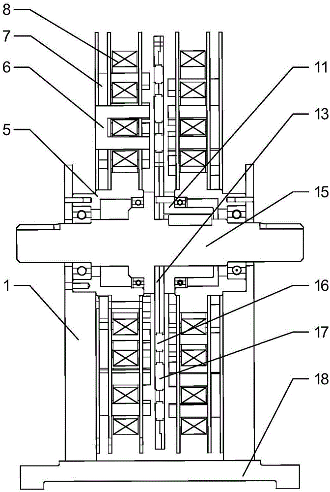
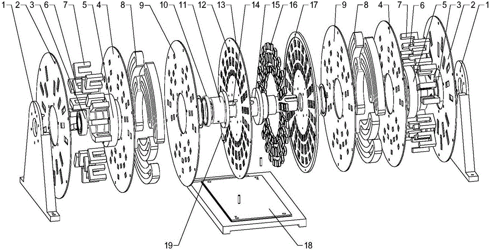
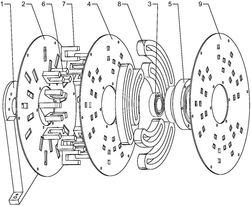
[0021] This embodiment is a disk-type double-cross-linkage magnetism-concentrating transverse field motor.

[0022] refer to Figure 1 to Figure 5 In this embodiment, the disk-type double-cross-link magnetic-gathering transverse field motor is composed of a rotor, a stator on both sides, a support 1, and a machine base 18. The two supports 1 and the machine base 18 are positioned and fixed by pins. The two supports 1 and the machine The seat 18 is installed vertically and symmetrically; the stators on each side are connected to the bracket 1 by pins, the stators on both sides differ in the circumferential direction by 360 / 2P mechanical angle, P is the number of pole pairs of the motor, and the axial length of the gap between the rotor and the stators on both sides is equal. Among them, the stator consists of a stator disc 2, a pay-off disc 4, a crimping disc 9, a primary C-type silicon steel lamination 6, a secondary C-type silicon steel lamination 7, an armature winding 8, a ...


PUM


Abstract

The invention discloses a disc-type double-cross-chain magnetic-concentrating transverse magnetic field motor. The motor is formed by one rotor and two stators whose two sides differ a 360/2P mechanical angle. The P is a motor pole pair number. The motor rotor is formed by two divided rotor discs provided with step holes, a permanent magnet and a shaft sleeve. Each motor stator is formed by an armature winding, a primary C-type silicon steel lamination and a secondary C-type silicon steel lamination which are reversely connected in series. The primary C-type silicon steel lamination and the secondary C-type silicon steel lamination differ the 360/2P mechanical angle along an axial direction. A periphery of an inner ring winding of the armature winding and an inner circumference of an outer ring winding are placed in tooth grooves of the primary C-type silicon steel lamination and the secondary C-type silicon steel lamination respectively along a radial direction. The stators and a support are positioned through a pin. The support and a motor seat are positioned and fixedly connected through the pin. In the motor structure, a difference angle of each phase of primary and secondary stator cores is the same with a circumferential difference angle of a rotor permanent magnet. Each pole of the permanent magnet of the rotor is used, a leakage flux of the motor is effectively reduced and a permanent magnet utilization rate is increased.

Description

technical field [0001] The invention relates to the technical field of permanent magnet motors, in particular to a disc-type double-interlinkage magnetic-condensation transverse magnetic field motor. Background technique [0002] With the development of electric drive technology, the market demand for low power, high torque, direct drive motors is more urgent. The traditional two-dimensional magnetic circuit motor, electromagnetic coupling, limits the increase of motor torque density. In 1986, Professor H.Weh of Germany proposed the design idea of ​​transverse magnetic field motor. The structure circuit and magnetic circuit of this motor are not on the same plane, which realizes electromagnetic decoupling. Increased motor torque density. [0003] Invention patent CN102820756A discloses "a disk-type three-phase magnetic concentration type transverse magnetic field permanent magnet motor". The permanent magnet motor adopts a double-sided stator structure, and the stators on ...

Claims


Application Information

Patent Timeline
Patent Type & Authority Applications(China)
IPC IPC(8): H02K21/24H02K21/02H02K1/27H02K1/28H02K1/18
CPCH02K1/185H02K1/27H02K1/28H02K21/026H02K21/24
Inventor 袁小庆郝凌霄吴建胜陈洋洋张党
Owner NORTHWESTERN POLYTECHNICAL UNIV
Why Eureka
Try Eureka