Image processing device and method and monitoring system
An image processing device and current image technology, applied in the field of image processing, can solve problems such as determining foreground images, and achieve the effect of improving accuracy
- Summary
- Abstract
- Description
- Claims
- Application Information
AI Technical Summary
Problems solved by technology
Method used
Image

Examples
Embodiment approach
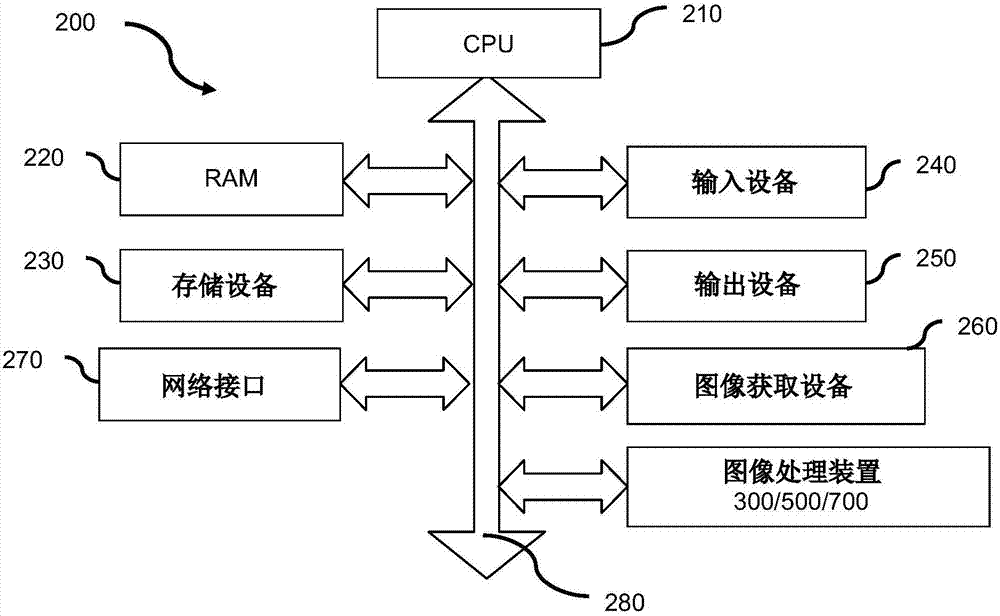
[0033] For the above-mentioned first embodiment, the hardware structure 200 includes, for example, a CPU 210, a random access memory (RAM) 220, a storage device 230, an input device 240, an output device 250, an image acquisition device 260, a network interface 270, and a system bus 280 , and an image processing device 300 / 500 / 700. For the above-mentioned second implementation manner, for example, the hardware structure 200 will not include the above-mentioned image processing apparatus 300 / 500 / 700. And, in this embodiment, it can be pre-installed in the storage device 230 and will be referred to later Figure 8 / Figure 9 The described program corresponds to the image processing of the present invention, and when the CPU 210 needs to execute the corresponding program, the installed program can be loaded from the storage device 230 to the RAM 220 .
[0034] The CPU 210 is any suitable programmable control device (such as a processor, etc.), and executes subsequent various ...
PUM
 Abstract
Description
Claims
Application Information