drive unit

A driving device and linkage technology, applied in the fields of medical science, surgery, diagnosis, etc., can solve the problem of reduced position accuracy and high change, and achieve the effect of suppressing overload

Active Publication Date: 2019-07-05
OLYMPUS CORP
View PDF8 Cites 0 Cited by
  • Summary
  • Abstract
  • Description
  • Claims
  • Application Information

AI Technical Summary

Problems solved by technology

As a result, there arises the problem that the positional accuracy decreases when the optical filter is arranged at a predetermined position, or the possibility of failure due to overload of the drive motor increases.

Method used


Image

  • drive unit
  • drive unit
  • drive unit

Examples


Embodiment Construction

[0019] Hereinafter, the present invention will be described with reference to the illustrated embodiments. The drawings used in the following description are schematic, and the dimensional relationship or scale of each member may be different for each constituent element in order to show each constituent element in a size that can be recognized on the drawing. show. Therefore, the number of constituent elements, the shape of the constituent elements, the ratio of the size of the constituent elements, and the relative positional relationship of the constituent elements described in each of the drawings according to the present invention are not limited to those shown in the drawings.

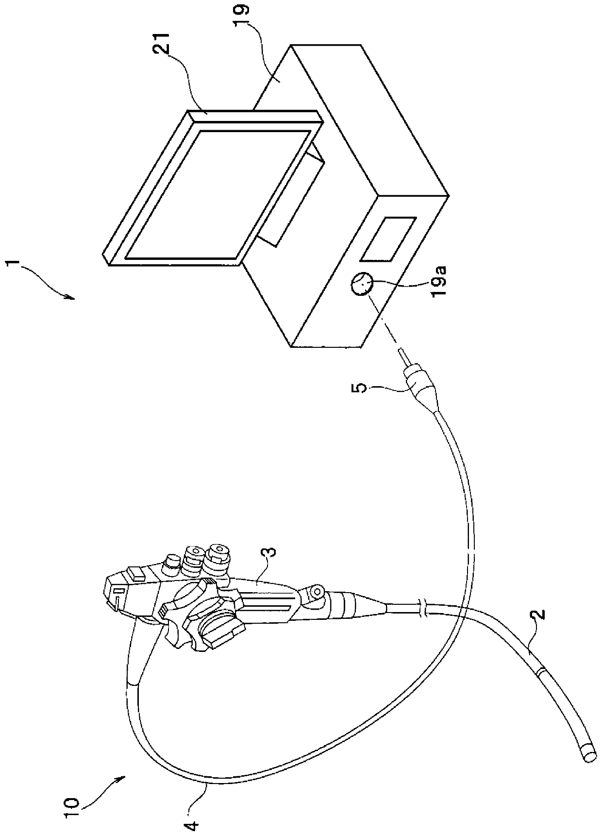
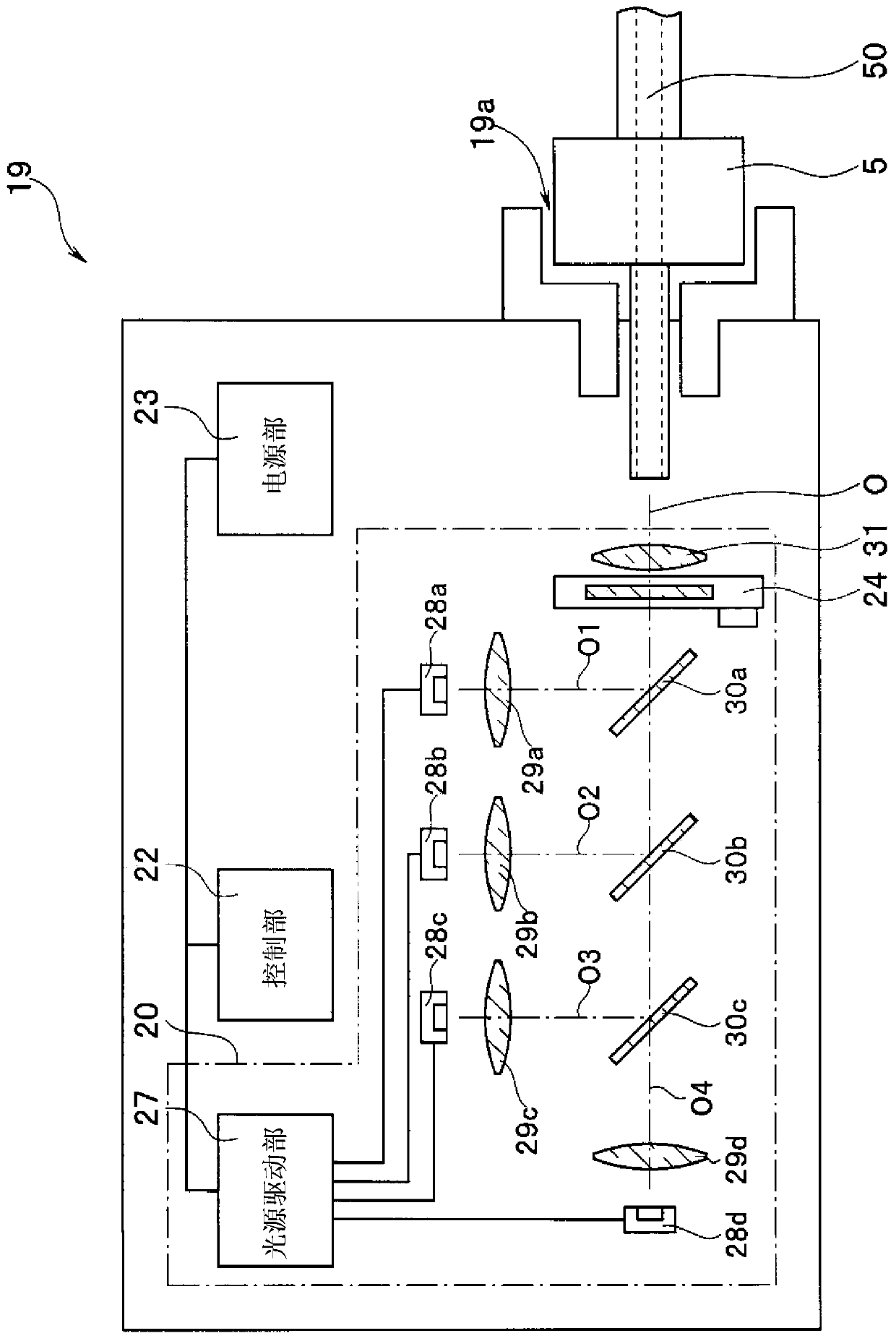
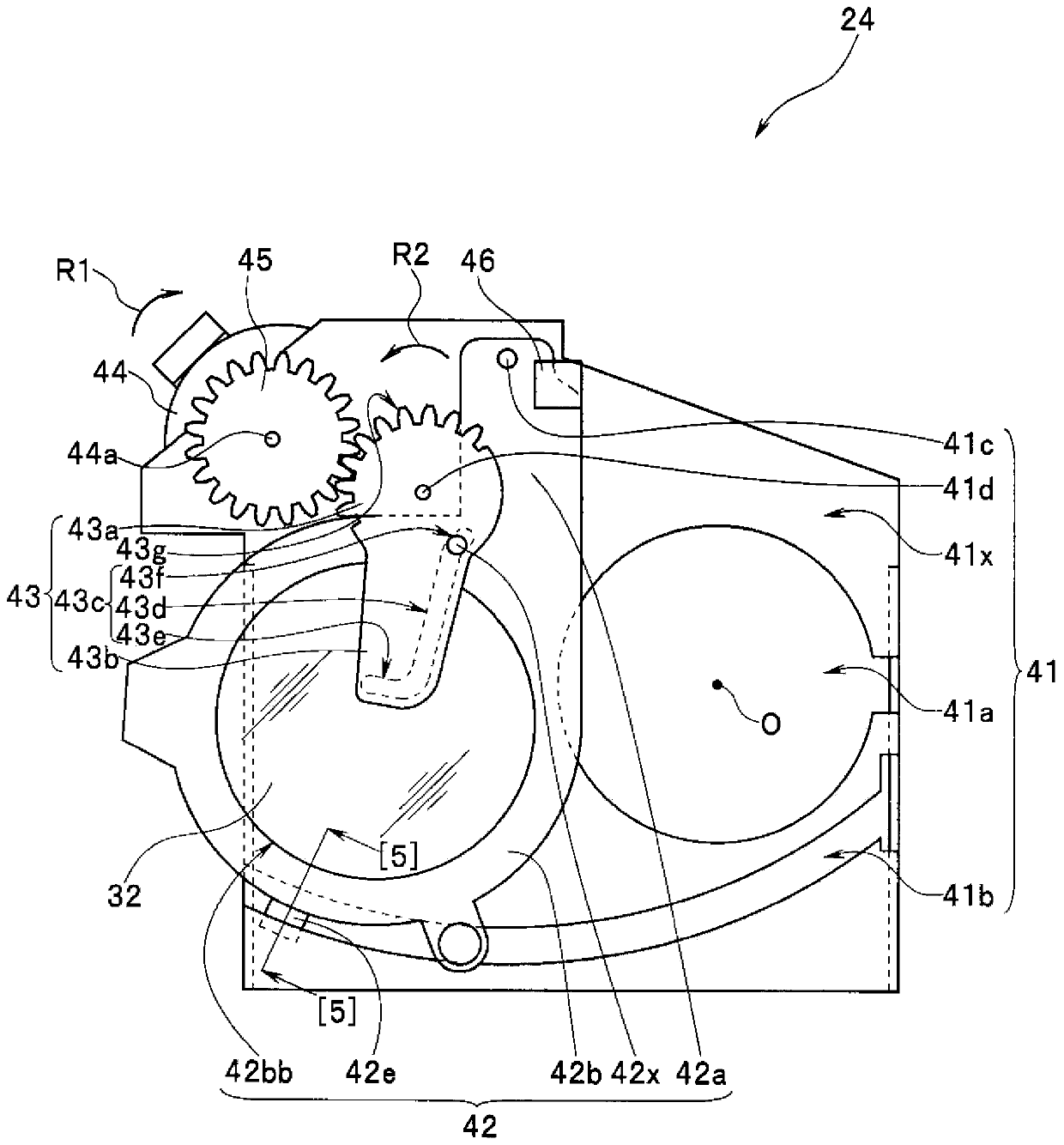
[0020] Figure 1 to Figure 5 It is a figure which shows one Embodiment of this invention. in, figure 1 It is a schematic perspective view showing the overall configuration of an endoscope system including a light source device for an endoscope having the driving device according to the present...


PUM


Abstract

The object of the present invention is to provide a driving device for an observation light switching mechanism capable of suppressing the overload of the driving motor and realizing miniaturization. Therefore, the driving device of the present invention has: a filter part (42), which is configured to generate The optical filter (32) of the light of wavelength characteristic, this filter part (42) can dispose the optical filter at the first position and the second position different from the first position; Convex part (42x), it is arranged on On the filter part; the transmission part (43), which has a first groove part (43d) for the convex part to contact, and the transmission part (43) rotates the convex part along the predetermined rotation axis (41d) Move along the first groove, so that the optical filter moves from the first position to the second position; and the second groove (43e), which is arranged on the transfer part, moves along the optical filter to the second position The tangential direction of the convex part centered on the rotation axis of the transmission part in the state is set.

Description

technical field [0001] The present invention relates to a drive device for an observation light switching mechanism for switching observation light by inserting and removing an optical filter on an optical path in a light source device for an endoscope. Background technique [0002] Conventionally, endoscopes having an insertion portion in the shape of an elongated tube have been widely used in, for example, the medical field and the industrial field. Among them, the medical endoscope used in the medical field is configured so that the insertion part can be inserted into the body cavity of the subject, such as a living body, to observe the organs, etc., or it can be inserted into the endoscope if necessary The treatment tool penetrates the treatment tool inserted into the channel to perform various treatments on the organ or the like. In addition, industrial endoscopes used in the industrial field are configured so that the insertion part can be inserted into a device or eq...

Claims


Application Information

Patent Timeline
Patent Type & Authority Patents(China)
IPC IPC(8): A61B1/06A61B1/00
CPCA61B1/0655A61B1/0638A61B1/0646A61B1/00A61B1/00013A61B1/00048A61B1/0005A61B1/00188A61B1/043A61B1/045A61B1/053G02B23/26
Inventor 代田雄高渡部正晃端山贵洋熊田鲇子
Owner OLYMPUS CORP
Why Eureka
Try Eureka