A self-stirring fermenter

A fermentation tank and hopper technology, applied in the field of self-stirring fermentation tanks, can solve the problems of heavy labor, increased chances of contamination, inconvenient users, etc., and achieve the effect of improving work efficiency and reducing manual labor

Active Publication Date: 2019-05-07
山东恒德消防设备有限公司
View PDF5 Cites 0 Cited by
  • Summary
  • Abstract
  • Description
  • Claims
  • Application Information

AI Technical Summary

Problems solved by technology

[0002] At present, fermentation tanks are often used in some fermented soya bean and sauce fermentation plants. However, sauces need to be stirred regularly during the fermentation process to increase the fermentation effect. In the prior art, manual operation is generally used for regular stirring, and the labor force is relatively high. It is large and needs to open the sealing cover when stirring, which is not only cumbersome to operate but also seriously affects the fermentation effect, and increases the chance of contamination, which cannot guarantee the food safety of fermented food. At the same time, most of the existing fermentation tanks are designed as a whole. When the fermented food is taken out, it is difficult, which brings inconvenience to the user and cannot meet the existing needs

Method used


Image

  • A self-stirring fermenter
  • A self-stirring fermenter
  • A self-stirring fermenter

Examples


Embodiment Construction

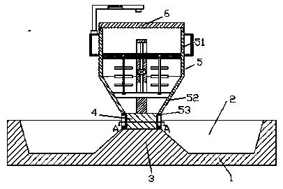
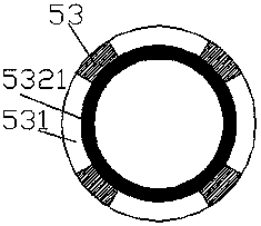
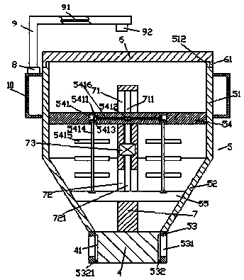
[0022] Such as Figure 1-Figure 5 As shown, a self-stirring fermenter of the present invention includes a ring base 1 and a fermentation tank 5 arranged above the ring base 1, the ring base 1 is provided with a ring groove 2, and the inside of the ring groove 2 is The end is provided with a protruding platform 3, the top of the protruding platform 3 is provided with a base body 4, and the fermentation tank 5 is composed of a first bucket storehouse 51, a second bucket storehouse 52 and a third bucket storehouse 53, and the outside of the base body 4 is provided with There is a sliding connection groove 41, the third bucket 53 is fitted on the outer side of the base body 4 and the edge of the inner bottom is provided with a protruding ring 532 that penetrates into the sliding connection groove 41 and is connected by a sliding connection. Ports 531 are provided on the outer walls of the four ends of the bucket 53, and the top end of the base body 4 is provided with a top column ...


PUM


Abstract

The invention discloses an automatic-stirring fermentation tank. The automatic-stirring fermentation tank comprises an annular seat and a fermentation tank arranged on the annular seat, wherein an annular groove is formed in the annular seat; a protruding table is arranged at the middle end in the annular groove; a basal body is arranged at the top of the protruding table; the fermentation tank consists of a first hopper, a second hopper and a third hopper; a sliding connecting groove is formed in the outer part of the basal body; the third hopper sleeves the outer side of the basal body, and a protruding ring which penetrates into the sliding connecting groove and is in sliding fit connection with the sliding connecting groove is arranged at the inner bottom edge of the third hopper; ports are separately arranged at the outer walls of four end surfaces of the third hopper; a top column which extends upwards is arranged on the top end surface of the basal body; the top extending section of the top column passes through the second hopper and penetrates into the first hopper; a first guiding groove is formed in the top column of the first hopper, and a second guiding groove is formed in the top column of the second hopper; and a first electric rotating machine is arranged in the top column between the first guiding groove and the second guiding groove. The automatic-stirring fermentation tank disclosed by the invention is simple in structure, convenient to operate and reasonable in design, can automatically control stirring and material discharging, and is simple and convenient to clean, so that the working efficiency and the using hygienic cleanness are improved.

Description

technical field [0001] The invention relates to the technical field of food fermentation, in particular to a self-stirring fermentation tank. Background technique [0002] At present, fermentation tanks are often used in some fermented soya bean and sauce fermentation plants. However, sauces need to be stirred regularly during the fermentation process to increase the fermentation effect. In the prior art, manual operation is generally used for regular stirring, and the labor force is relatively high. It is large and needs to open the sealing cover when stirring, which is not only cumbersome to operate but also seriously affects the fermentation effect, and increases the chance of contamination, which cannot guarantee the food safety of fermented food. At the same time, most of the existing fermentation tanks are designed as a whole. When the fermented food is taken out, it is more difficult, which brings inconvenience to the user and cannot meet the existing needs. Content...

Claims


Application Information

Patent Timeline
Patent Type & Authority Patents(China)
IPC IPC(8): A23P30/00A23P30/40A23L5/10
Inventor 叶棋刚
Owner 山东恒德消防设备有限公司
Why Eureka
Try Eureka