
Glue dispending machine

A glue dispensing machine and glue dispensing technology, applied in the field of glue dispensing machine, can solve the problems of high labor cost, easy sticking of rubber hose, low work efficiency, etc., and achieve the effect of high degree of automation, simple and convenient operation, and reduced labor cost.

Active Publication Date: 2017-12-01
上海胜华波汽车电器有限公司
View PDF20 Cites 2 Cited by
  • Summary
  • Abstract
  • Description
  • Claims
  • Application Information

AI Technical Summary

Problems solved by technology

However, the work efficiency of this method is low, and the dispensing effect is not ideal, and the labor cost is high
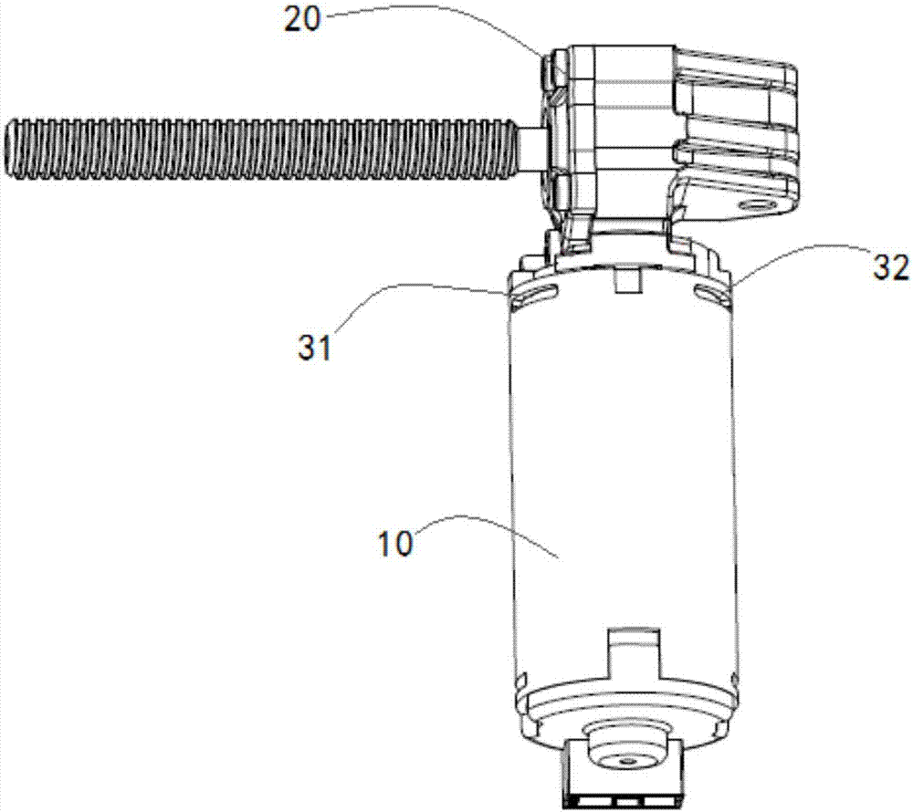
There are also dispensing machines used to realize dispensing at the two riveting points 31 and 32 at the junction of the automotive micro-motor casing 10 and the aluminum alloy reduction box body 20, but the dispensing machines currently on the market basically use the peristaltic method. And XYZ mobile platform dispensing, the hose is often sticky, glue cannot be released, and it is not easy to detect whether the glue is released

Method used


Image

  • Glue dispending machine
  • Glue dispending machine
  • Glue dispending machine

Examples


Embodiment Construction

[0037] In order to make the technical means, creative features, goals and effects achieved by the present invention easy to understand, the present invention will be further described below in conjunction with specific illustrations.

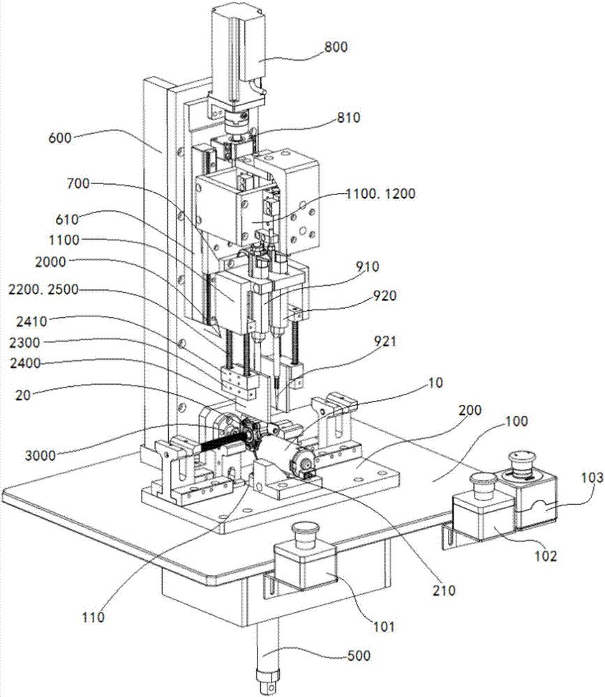
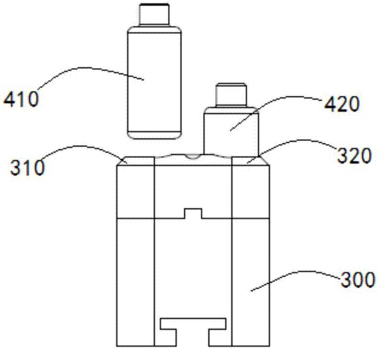
[0038] Referring to the accompanying drawings, a glue dispensing machine of the present invention includes a working platform 100, a positioning base 200, a glue cartridge placement frame 300, glue cartridges 410, 420, a glue feeding cylinder 500, a mounting column 600, a glue dispensing installation slide 700, Glue dispensing servo motor 800, pipettes 910, 920, glue suction cylinder 1100, glue discharge cylinder 1200 and PLC controller (not shown in the figure).

[0039] A through hole 110 is defined on the working platform 100 . The positioning base 200 is arranged on the working platform 100 and is located at the through hole 110, and a V-shaped groove 210 is formed on the positioning base 200, which is used for positioning the assembly assem...


PUM


Abstract

The invention discloses a glue dispensing machine. The glue dispensing machine comprises a working platform, a positioning base, a mounting vertical column, a glue dispensing mounting sliding seat, a glue dispensing servo motor, liquid moving devices, a glue absorbing air cylinder, a glue discharging air cylinder and a PLC, wherein the positioning base is arranged on a working platform; the mounting vertical column is vertically arranged on the working platform and positioned on one side of the positioning base; the glue dispensing mounting sliding seat is installed on a sliding rail of the vertical column in a sliding configuration mode and positioned above the positioning base; the glue dispensing servo motor is mounted on a mounting vertical column and is connected with the glue dispensing mounting sliding seat trough a transmission mechanism; the liquid moving devices are horizontally mounted on the glue dispensing mounting sliding seat at intervals; the glue absorbing air cylinder is installed in the glue dispensing mounting sliding seat; the glue discharging air cylinder is installed in the glue dispensing mounting sliding seat; and the PLC is connected with the glue dispensing servo motor, the glue absorbing air cylinder and the glue discharging air cylinder. According to the glue dispensing machine, the liquid moving devices are adopted for glue dispensing, glue bonding phenomenon is not easy to occur in the liquid moving devices, just a glue dispensing needle is replaced if bonding is appeared in the glue dispensing needle, operation is simple and convenient.

Description

technical field [0001] The invention relates to the technical field of glue dispensing machines, in particular to a glue dispensing machine for riveting joints between automobile micro-motor casings and reduction box bodies. Background technique [0002] see figure 1 , shown in the figure is a schematic diagram of the assembly of the automobile micro-motor casing and the aluminum alloy reduction box body. The automobile micro-motor casing 10 and the aluminum alloy reduction box body 20 are connected by riveting. There are two riveting points 31 and 32 at the junction of the aluminum alloy reduction box body 20. However, due to the dimensional tolerances of the parts, there is a certain looseness after the automotive micro-motor casing 10 and the aluminum alloy reduction box body 20 are riveted. 502 glue fills the loose gap between the automobile micro-motor casing 10 and the aluminum alloy reduction box 20 to ensure the strength and stability of riveting. [0003] At prese...

Claims


Application Information

Patent Timeline
Patent Type & Authority Applications(China)
IPC IPC(8): B05C5/02B05C13/02B05C11/10
CPCB05C5/02B05C11/1002B05C11/1015B05C13/02
Inventor 丁丹芹刘代友王佳佳
Owner 上海胜华波汽车电器有限公司
Learn More