Conveying equipment for to-be-machined laminated board

A technology of conveying equipment and veneer, which is applied to wood processing appliances, joining of wooden veneers, veneer presses, etc., can solve the problems of high physical consumption of feeding personnel, low feeding efficiency and low conveying accuracy, etc. Achieve high work efficiency, reduce unqualified product rate, and high conveying precision.

Active Publication Date: 2017-12-01
LIUZHOU VOCATIONAL & TECHN COLLEGE
View PDF4 Cites 0 Cited by
  • Summary
  • Abstract
  • Description
  • Claims
  • Application Information

AI Technical Summary

Problems solved by technology

In the process of loading and unloading the hot press, there are currently two main methods: 1. Manual loading and unloading: the feeding personnel consume a lot of energy and low efficiency; 2. Belt conveying equipment: the feeding efficiency is not high, and the structure is backward. The conveying accuracy is low, and the paper sticks to the belt during loading and unloading, which may easily lead to the production of unqualified products

Method used


Image

  • Conveying equipment for to-be-machined laminated board
  • Conveying equipment for to-be-machined laminated board
  • Conveying equipment for to-be-machined laminated board

Examples


Embodiment 1

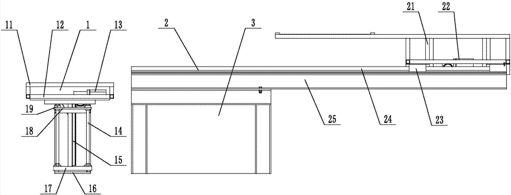
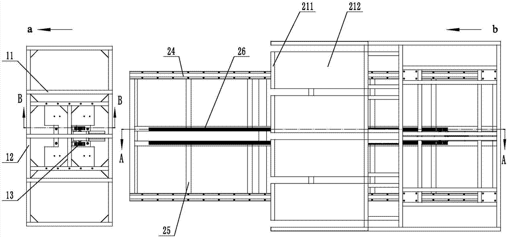
[0027] like Figure 1-2 , Shown in 4, a kind of conveying equipment of veneer to be processed, it comprises jacking mechanism 1, conveying mechanism 2 and conveying mechanism supporting frame 3; Conveying mechanism supporting frame 3 is fixed on the ground; Jacking mechanism 1 is located at conveying mechanism 2, the jacking mechanism 1 includes a jacking mechanism frame 16, a supporting backing plate 18 is provided above the jacking mechanism frame 16, a lifting platform 12 is provided on the supporting backing plate 18, and a lifting platform drive is provided in the middle of the supporting backing plate 18. Part 13, the lifting platform driving part 13 drives the lifting platform 12 to move up and down, and five materials are evenly spaced on the lifting platform 12 to lift up the bracket 11; the conveying mechanism 2 includes a conveying mechanism base 25, and the conveying mechanism base 25 is installed on the conveying mechanism supporting frame 3 , the conveying mechan...

Embodiment 2

[0029] like Figure 1-2 , 4-5, on the basis of embodiment 1, jacking mechanism 1 also includes linear guide rail I14, linear bearing 19, linear guide rail I connecting rod 17 and jacking mechanism rack 15, linear guide rail I14 and linear bearing 19 Flexible connection, the linear bearing 19 is set on the support pad 18, one end of the linear guide rail I14 is connected with the lifting platform 12, and the other end passes through the support pad 18 to connect with the linear guide rail I connecting rod 17; the rack 15 of the jacking mechanism is set on In the jacking mechanism frame 16, one end passes through the support pad 18 and is connected with the lifting platform 12, and the other end is connected with the bottom plate of the jacking mechanism frame 16, and the lifting platform driver 13 is rollingly connected with the jacking mechanism rack 15. Lifting table driver 13 comprises servo motor gear 131, reducer 132 and jacking mechanism servo motor 133, and jacking mecha...

Embodiment 3

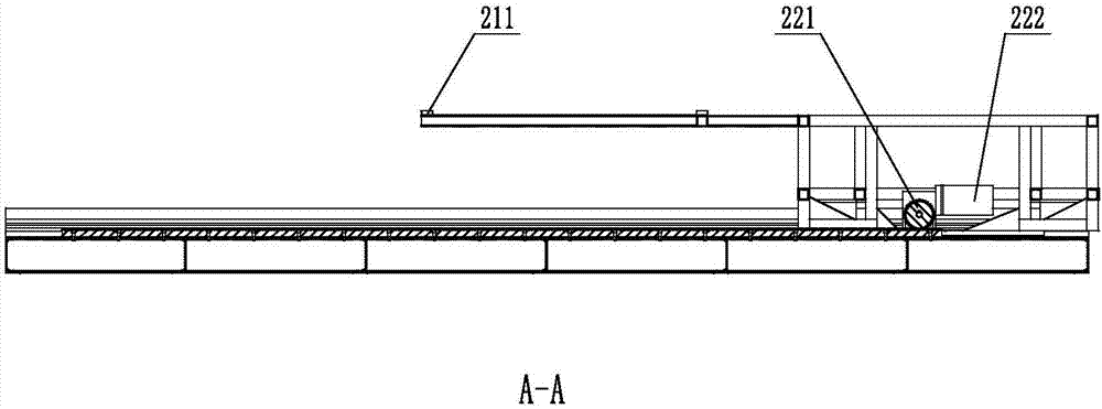
[0031] like Figure 1-4 As shown, on the basis of Embodiment 1, sliders I23 are arranged on the left and right sides below the rear part of the material placement bracket 21 of the conveying mechanism 2, and the sliders I23 are movably connected with the linear guide rail II24, and the linear guide rail II24 is arranged on the base of the conveying mechanism 25 Above, the middle part of the conveying mechanism base 25 is provided with a conveying mechanism rack 26 , and the conveying mechanism driving member 22 is in rolling connection with the conveying mechanism rack 26 . The driving member 22 of the conveying mechanism includes a stepping motor 222 and a stepping motor gear 221 , the power of the stepping motor 222 is output to the stepping motor gear 221 , and the stepping motor gear 221 is rollingly connected with the rack 26 of the conveying mechanism.


PUM


Abstract

The invention discloses conveying equipment for a to-be-machined laminated board. The conveying equipment comprises a jacking mechanism (1), a conveying mechanism (2) and a conveying mechanism supporting frame (3). The conveying mechanism supporting frame (3) is fixed to the ground; the jacking mechanism (1) is arranged in front of the conveying mechanism (2); the jacking mechanism (1) comprises a jacking mechanism framework (16); a supporting cushion plate (18) is arranged on the upper portion of the jacking mechanism framework (16); a lifting table (12) is arranged on the supporting cushion plate (18); a lifting table driving piece (13) is arranged in the middle of the supporting cushion plate (18); the lifting table driving piece (13) drives the lifting table (12) to move up and down; and a plurality of material jacking supports (11) are uniformly arranged on the lifting table (12) at intervals. The conveying equipment has the advantages that the working efficiency is high, energy consumption is reduced, manpower is saved, conveying precision is high, and the product qualification rate can be increased.

Description

technical field [0001] The invention belongs to the field of automatic feeding, and in particular relates to a conveying device for veneers to be processed. Background technique [0002] In the wood processing and manufacturing industry, especially the hot-pressed veneer production industry of wood boards, the degree of automation of equipment is relatively backward, and it is basically manual. In the process of loading and unloading the hot press, there are currently two main methods: 1. Manual loading and unloading: the feeding personnel consume a lot of energy and low efficiency; 2. Belt conveying equipment: the feeding efficiency is not high, and the structure is backward. The conveying accuracy is low, and the paper sticks to the belt during loading and unloading, which may easily lead to the production of unqualified products. Contents of the invention [0003] The object of the present invention is to solve the above-mentioned technical problems, and provide a conv...

Claims


Application Information

Patent Timeline
Patent Type & Authority Applications(China)
IPC IPC(8): B27D1/08B27D3/00B32B37/10B32B37/06
CPCB27D1/083B27D3/00B32B37/06B32B37/10
Inventor 陈晖吴兆辉罗喻允杨寅
Owner LIUZHOU VOCATIONAL & TECHN COLLEGE
Why Eureka
Try Eureka