
Mixed printing head type 3D printer

A 3D printer and print head technology, applied in 3D object support structures, additive manufacturing, coating devices, etc., can solve problems such as poor separation and mixing of liquid plastics, reduced connectivity of finished products, and reduced structural strength.

Pending Publication Date: 2017-12-01
青岛三易三维技术有限公司
View PDF5 Cites 3 Cited by
  • Summary
  • Abstract
  • Description
  • Claims
  • Application Information

AI Technical Summary

Problems solved by technology

[0003] The print head of the existing 3D printer, the print head is connected to the print head support mechanism, the print head includes a heat dissipation block, a heating block and a throat, etc., and the bottom of the throat is connected to the nozzle, and the existing nozzles are generally hollow inside. Although the steel pipe and steel pipe nozzle can realize the ejection of liquid plastic, in the actual use process, because the liquid plastic used for 3D printing is heated by the heating block, the heating will be uneven, so that the liquid plastic in the nozzle When spraying, there will be poor separation. The separation and mixing of liquid plastics are not good, so that the connection of the finished product will be reduced during the printing process of the 3D printer, which will directly affect the quality of the 3D printed product. Although 3D There is not much difference in the appearance of the printed finished product, but the structural strength will be seriously reduced

Method used


Image

  • Mixed printing head type 3D printer
  • Mixed printing head type 3D printer
  • Mixed printing head type 3D printer

Examples


Embodiment Construction

[0021] The present invention is described in detail below in conjunction with accompanying drawing:

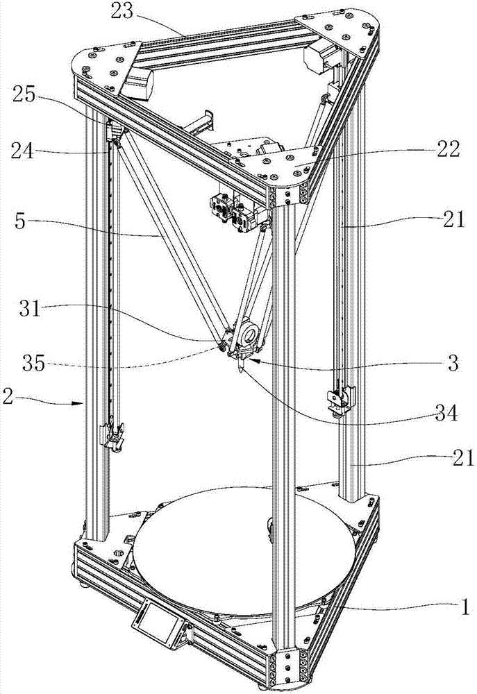
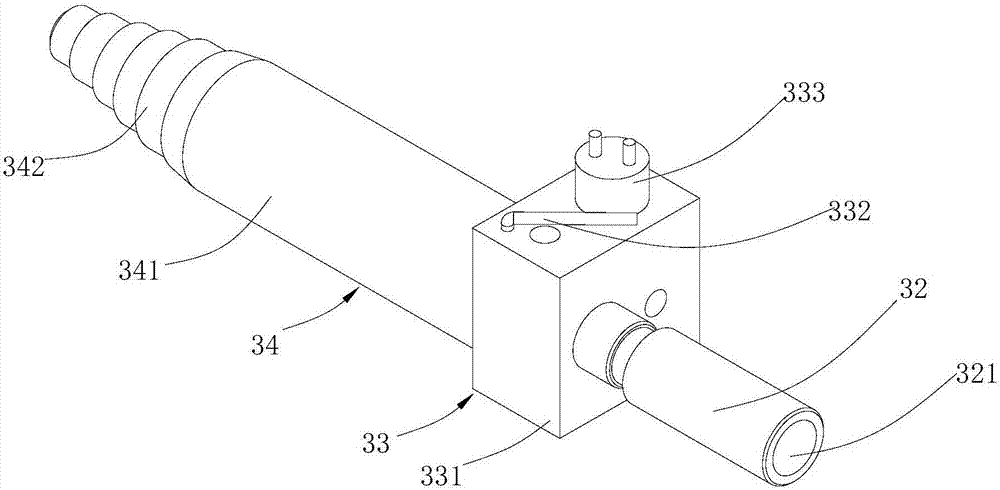
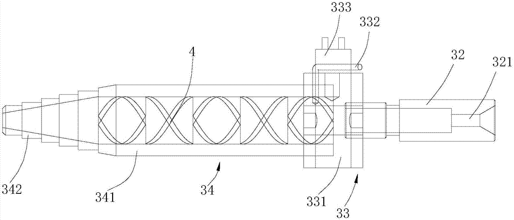
[0022] combine Figure 1 to Figure 5 , a mixed print head type 3D printer, including a base 1, a support 2, a print head mechanism 3 and a static mixer 4, the base 1 is connected to the support 2, and the support 2 is connected to the print head mechanism 3 through a connecting rod 5. The bracket 2 includes three columns 21 , three connecting heads 22 and three beams 23 , the three columns 21 are connected with the three connecting heads 22 , and the three beams 23 are connected between the three connecting heads 22 . A slideway 24 is arranged on the column 21 , and one end of the connecting rod 5 is connected with a slide block 25 on the slideway 24 .

[0023] The print head mechanism 3 includes a positioning plate 31, a throat 32, a heating assembly 33 and a nozzle 34. The positioning plate 31 is provided with a positioning rod 35, and the connecting rod 5 is connected with...


PUM


Abstract

The invention discloses a mixed printing head type 3D printer. The mixed printing head type 3D printer comprises a base, a support, a printing head mechanism and a static mixer; the base is connected with the support; the support is connected with the printing head mechanism through a connection rod; the printing head mechanism comprises a positioning board, a throat tube, a heating assembly and a nozzle; a positioning rod is arranged in the positioning board; a connection rod is connected with the positioning rod through a rotary shaft; the lower end of the middle of the positioning board is connected with the throat tube; the nozzle comprises a straight tube and a discharging tube; one end of the throat tube is connected with one end of the heating assembly; the other end of the heating assembly is connected with one end of the straight tube; the other end of the straight tube is connected with the discharging pipe; the static mixer comprises a first mixing portion, a second mixing portion and a clamping-connecting piece; the first mixing portion is connected with the second mixing portion; the outer wall of the first mixing portion is connected with the clamping-connecting piece; the first mixing portion is located in the straight tube; and the second mixing portion is located in the discharging pipe. Liquid plastic in the 3D printer can be sufficiently separated and stirred in the static mixer, the overall structure is simple and novel, and practicability is high.

Description

technical field [0001] The invention relates to the field of 3D printers, in particular to a hybrid printing head type 3D printer. Background technique [0002] As a forward-looking product in the 3D field, 3D printers have triggered a revolution in the world's manufacturing industry. Objects of any shape can be directly generated from computer graphics data without machining or molds. It has become a trend and is developing rapidly. It has been highly valued by various industries and institutions and applied to all walks of life. [0003] The print head of the existing 3D printer, the print head is connected to the print head support mechanism, the print head includes a heat dissipation block, a heating block and a throat, etc., and the bottom of the throat is connected to the nozzle, and the existing nozzles are generally hollow inside. Although the steel pipe and steel pipe nozzle can realize the ejection of liquid plastic, in the actual use process, because the liquid p...

Claims


Application Information

Patent Timeline
IPC IPC(8): B29C64/112B29C64/209B29C64/295B33Y30/00
CPCB33Y30/00
Inventor 张国庆
Owner 青岛三易三维技术有限公司
Learn More