
Single air gun salute and tandem body of single air gun salute

A technology of serial body and salute, applied in the field of salute, can solve the problems of environmental pollution, danger, open flames, etc., and achieve the effect of simple overall structure and environmental protection

Pending Publication Date: 2017-12-01
广州市君尚环保科技有限公司
View PDF4 Cites 0 Cited by
  • Summary
  • Abstract
  • Description
  • Claims
  • Application Information

AI Technical Summary

Problems solved by technology

These fuel salutes use gaseous fuel or liquid fuel, and there will be an open flame when used, which has certain dangers and environmental pollution.

Method used


Image

  • Single air gun salute and tandem body of single air gun salute
  • Single air gun salute and tandem body of single air gun salute
  • Single air gun salute and tandem body of single air gun salute

Examples


Embodiment 1

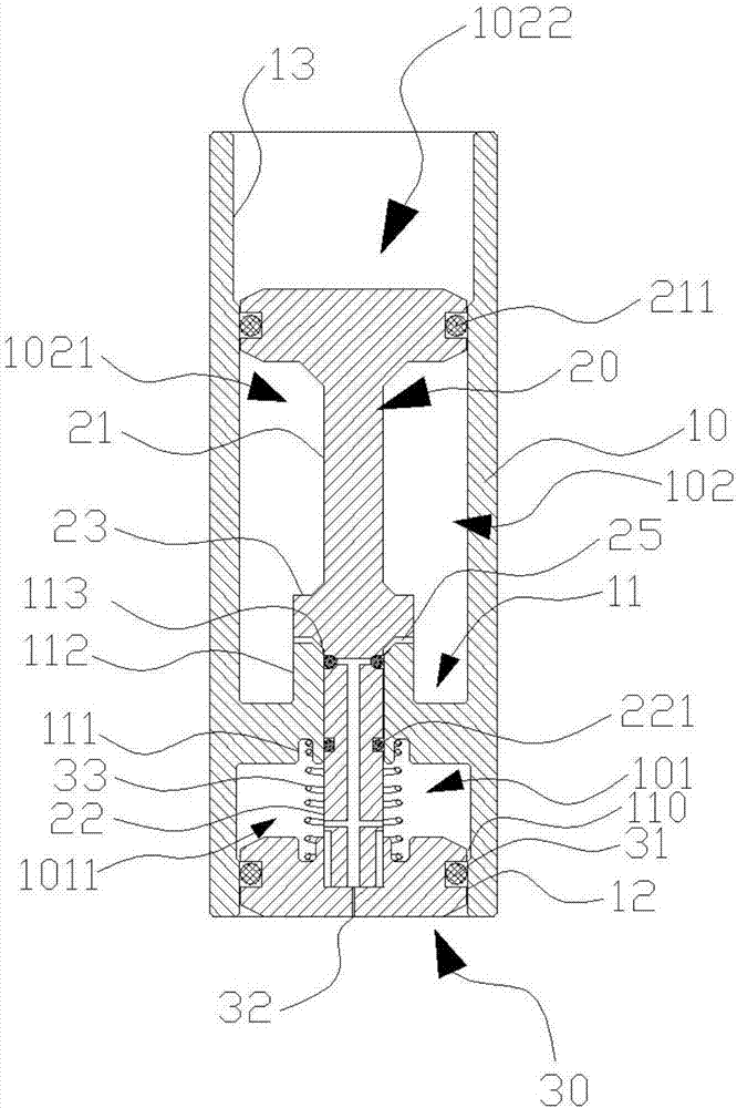
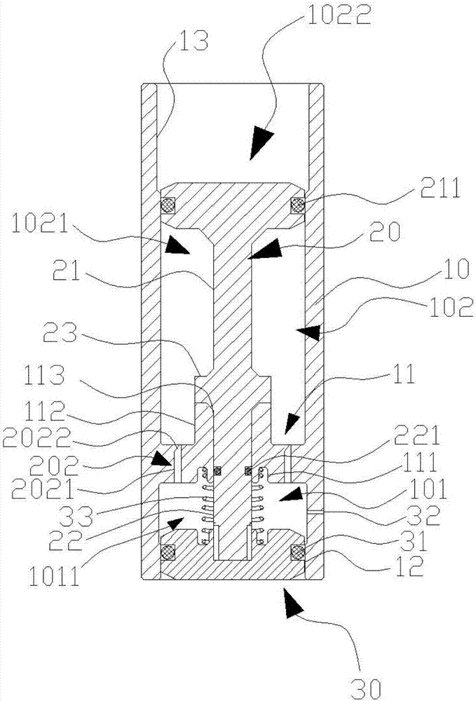
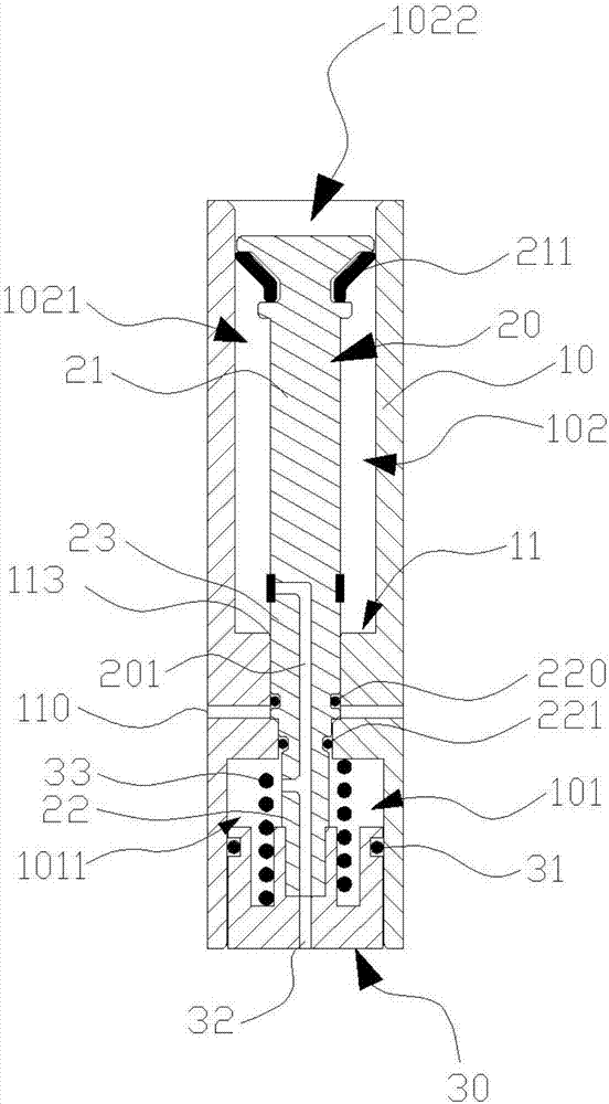
[0025] See figure 1 In this embodiment, the air salute unit includes a gun body 10, a sliding shaft 20 and a gun cover 30. Combined reference Figure 4 The gun body 10 has a hollow structure with open ends. A partition wall 11 is formed in the inner cavity of the gun body 10 near the bottom end to divide the gun body 10 into a first inner cavity section 101 at the bottom end and a first inner cavity section 101 at the top end. The second inner cavity section 102; the center of the partition wall 11 forms an annular groove 111 on the side adjacent to the first inner cavity section 101, the center of the partition wall 11 forms a bearing boss 112 on the side adjacent to the second inner cavity section 102, bearing The center of the boss 112 is formed with an axis hole 113 that penetrates the partition wall 11, and the axis hole 113 communicates with the first inner cavity section 101 and the second cavity section 102; or the center of the partition wall 11 does not need to form th...

Embodiment 2

[0035] See Figure 7 , The air salute series body of the present invention includes an air pump 2001, an air storage device 2002, an overflow valve 2003, a number of one-way valves 2004, a number of solenoid valves 2005, and a number of the air salute units 2006, each air salute unit 2006 Correspondingly connect a one-way valve 2004 and a solenoid valve 2005. In this embodiment, the air pump 2001 can also directly inflate the air salute without using the air storage device 2002, but using the air storage device 2002 can stabilize the air pressure when the air salute unit 2006 is continuously sounding.

[0036] When working, start the air pump 2001 to inflate the gas storage device 2002. The gas storage device 2002 plays a role of storing gas and buffering. The gas storage device 2002 and the overflow valve 2003 are connected through the gas pipe. The overflow valve 2003 plays a safety protection role, and the overflow valve 2003 There is a pressure gauge, which can read the pres...


PUM


Abstract

The invention provides a single air gun salute which comprises a salute body, a sliding shaft and a salute cover, wherein the salute body is in a hollow structure with two opened ends, the inner chamber of the salute body forms a gap wall, and the salute is divided into a first inner chamber segment and a second inner chamber segment by the gap wall; the sliding shaft penetrates through the gap wall to be arranged in the salute body, and the salute cover is fixedly connected with the sliding shaft; an upper air chamber is formed between the sealed end part of the sliding shaft and the gap wall and in the second inner chamber segment, and one end, back on to the gap wall, of the upper sealed end part of the salute forms an explosion mouth; a lower air chamber is formed between the salute cover and the gap wall and in the first inner chamber segment, and a one-way flowing air transmission channel is formed in the sliding shaft and communicates with the upper air chamber and the lower air chamber; vent holes are formed in the salute cover, and the sliding shaft moves up and down so as to communicate with or do not communicate with the explosion mouth. The single air gun salute has the advantages of simple structure, security and environmental protection and is reusable.

Description

Technical field [0001] The invention relates to the field of salutes, in particular to a safe and environmentally friendly air salute monomer and its series. Background technique [0002] The salute is a cannon fired when a grand ceremony is held or when guests are welcome to salute, to convey respect. However, most of the traditional fuel salutes on the market are currently on the market. By filling the barrel with gaseous fuel or volatile liquid fuel, and then energizing the ignition electrode, electric sparks are used to ignite the gaseous fuel in the barrel or easily. The volatile liquid fuel makes a noise. These fuel salutes use gas fuel or liquid fuel, and there will be open flames during use, which is dangerous and environmentally polluting. Summary of the invention [0003] In view of the above, it is necessary for the present invention to provide an air salute that can replace fuel salute, can be reused, and is safe and environmentally friendly. [0004] An air salute un...

Claims


Application Information

Patent Timeline
IPC IPC(8): F42B4/22
CPCF42B4/22
Inventor 王新明
Owner 广州市君尚环保科技有限公司
Learn More