
Testing device for simulating drainage seepage state of tunnel

A tunnel drainage and test device technology, which is applied in the direction of measuring device, permeability/surface area analysis, suspension and porous material analysis, etc., can solve the difficult tunnel surrounding rock seepage field distribution, difficult rainfall and drainage simultaneous monitoring and other problems to achieve the effect of solving unclear understanding

Active Publication Date: 2017-12-01
ZHEJIANG UNIV
View PDF10 Cites 4 Cited by
  • Summary
  • Abstract
  • Description
  • Claims
  • Application Information

AI Technical Summary

Problems solved by technology

As the tunnel is a concealed project, the drainage facilities of the tunnel are generally buried in the surrounding rock, and it is difficult for engineering and technical personnel to have a clear understanding of the distribution of the seepage field of the surrounding rock of the tunnel with the current technical means.
In addition, although the rain gauge can monitor the change of rainfall intensity in the area near the tunnel in real time, the discharge flow of the tunnel drainage measures can only be estimated by setting up triangular weirs, etc. It is difficult to realize the simultaneous monitoring of rainfall and drainage, so as to obtain the rainfall intensity and Correlation between discharge

Method used


Image

  • Testing device for simulating drainage seepage state of tunnel
  • Testing device for simulating drainage seepage state of tunnel
  • Testing device for simulating drainage seepage state of tunnel

Examples


Embodiment Construction

[0031] The present invention will be further described in detail below in conjunction with the accompanying drawings and specific embodiments.

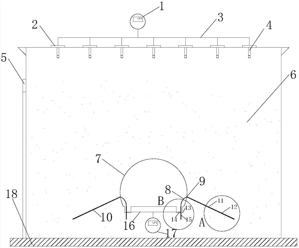
[0032] Such as Figure 1~5 As shown, the test device for simulating the tunnel drainage seepage state provided by the present invention includes a tunnel model box, a precipitation sprinkler system, a drainage system and a monitoring system; wherein,

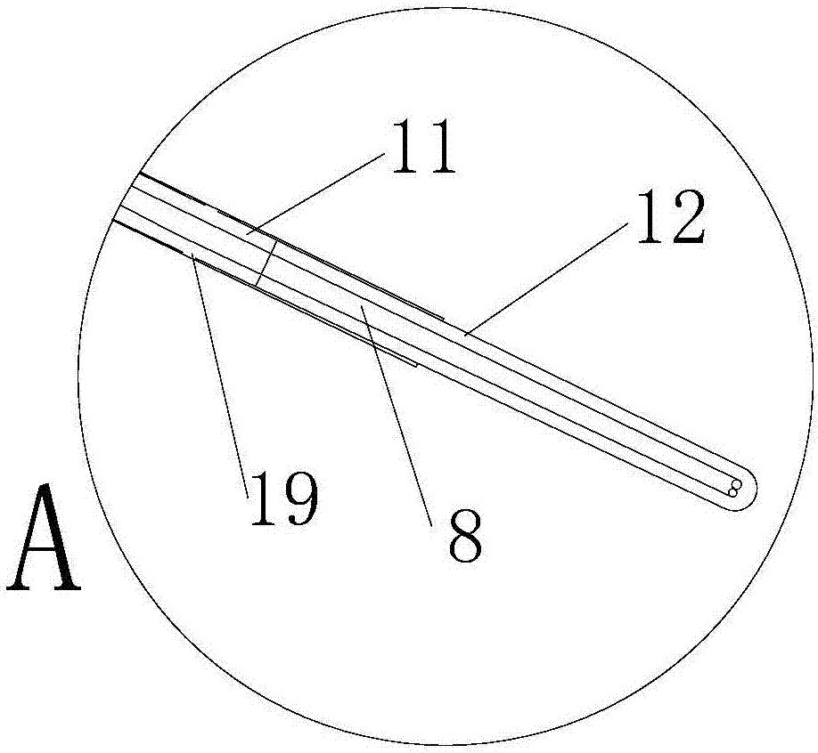
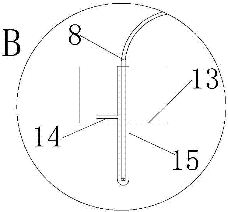
[0033] The tunnel model box body is a cuboid box body with an open top, and the bottom of the box body is provided with a steel frame for supporting the box body, and the inner space of the tunnel model box body is used for filling sand and soil 6 . The lower part of the front and rear side walls of the box is symmetrically provided with openings, and the upper arc-shaped plate and the lower bottom plate jointly form a through-hole 7 in the shape of a tunnel between the two openings; parallel grooves 13 (cross-section Rectangular), the groove 13 is provided with openings. The bottom, ...


PUM


Abstract

The invention relates to a tunnel drainage engineering technology, and aims to provide a testing device for simulating a drainage seepage state of a tunnel. The device comprises a tunnel model tank, a water spraying system, a drainage system and a monitoring system, wherein the tunnel model tank is a cuboid tank with an opening on the top, open holes are symmetrically formed in the lower part of front and rear sidewalls of the tank, and a penetrating through hole formed simulating the shape of the tunnel is formed by an upper curved plate and a lower bottom plate together between the two open holes; an internal space of the tank is filled with a soil body; a drainage pipeline is fixedly arranged on the penetrating through hole, and consists of an inclined drainage pipe, a vertical water collecting pipe and a hose for connecting the inclined drainage pipe and the vertical water collecting pipe. According to the device, changing conditions of a groundwater seepage field in a surrounding rock model of the tunnel under influence of different drainage systems can be directly simulated, seepage rules of groundwater of surrounding rocks of the tunnel under the action of drainage can be obtained through a testing result of the seepage state of the groundwater, and the problems of unclear identification and difficulty in field monitoring of the seepage state of the underground of the tunnel are effectively solved.

Description

technical field [0001] The invention belongs to tunnel drainage engineering technology. In particular, it relates to a test device for simulating the seepage state of tunnel drainage. Background technique [0002] In recent years, my country's highway transportation has developed rapidly, and the number and mileage of highway tunnels have continued to increase. Affected by the complex geological environment and hydrogeological conditions, the construction and operation of the tunnel still faces many engineering problems. Among them, the water leakage disease of the tunnel is a problem that plagues the operation and maintenance of the tunnel. [0003] Setting up drainage facilities inside the tunnel is one of the important means to control the water seepage in the tunnel at present. To study the change law of the seepage field of the groundwater in the surrounding rock area of ​​the tunnel under the action of different drainage measures, reveal the change of the discharge ...

Claims


Application Information

Patent Timeline
IPC IPC(8): G01N15/08
CPCG01N15/08Y02E10/20
Inventor 吕庆翁杨范雲鹤李海光郑俊洪叶南于洋孙红月尚岳全
Owner ZHEJIANG UNIV
Learn More