
Automatic sample injecting device for neutron activation

An automatic sampling and sample technology, applied in the direction of radiation measurement, instruments, etc., can solve the problems of high vibration and noise hazards, low automation, high labor intensity, etc., to reduce labor intensity, improve automation, and reduce on-site Hazardous Effects of Operation

Active Publication Date: 2017-12-01
INST OF NUCLEAR PHYSICS & CHEM CHINA ACADEMY OF
View PDF6 Cites 1 Cited by
  • Summary
  • Abstract
  • Description
  • Claims
  • Application Information

AI Technical Summary

Problems solved by technology

[0004] In order to overcome the low degree of automation existing in the sampling device in the prior art, the on-site operation of the staff is subject to high vibration and noise hazards and high labor intensity during the operation of the sampler, and it is difficult to meet the requirements of the highly automated sample transfer device for large batches. Insufficient requirements for automatic, fast and accurate irradiation and measurement of multiple types of samples, various irradiation conditions and especially the online automatic, fast and accurate irradiation and measurement of second-order short-lived nuclides, the present invention provides a neutron activation Sample Autosampler

Method used


Image

  • Automatic sample injecting device for neutron activation
  • Automatic sample injecting device for neutron activation
  • Automatic sample injecting device for neutron activation

Examples


Embodiment 1

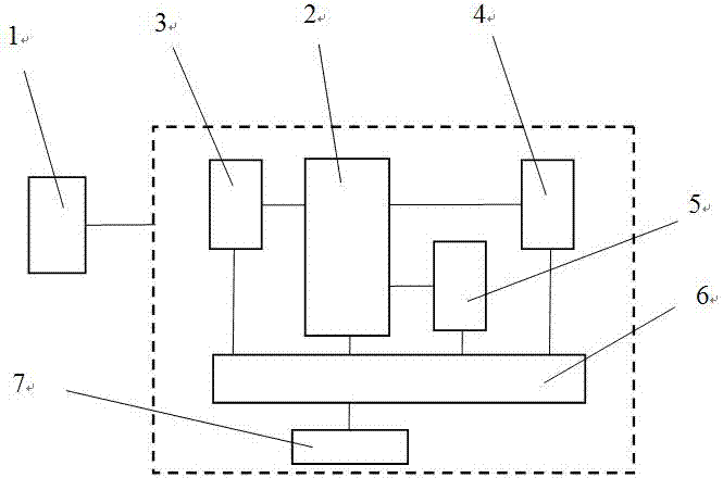
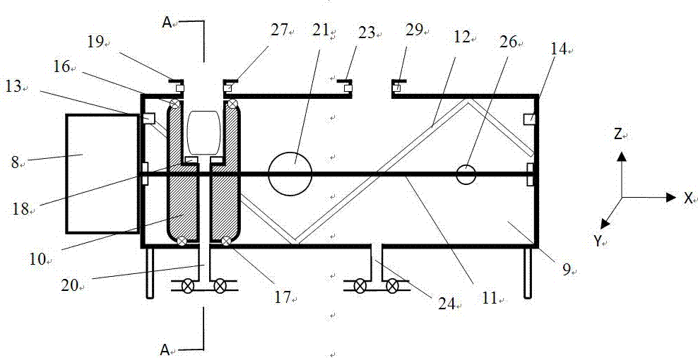
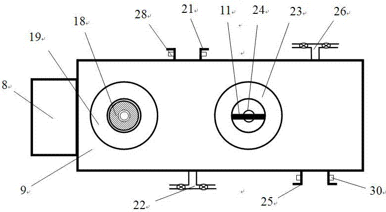
[0029] figure 1It is a block diagram of the overall structure of the sample automatic sampling device for neutron activation of the present invention, figure 2 It is a schematic diagram of the overall structure of the commutator in the present invention, image 3 It is a schematic diagram of the top view structure of the commutator in the present invention, Figure 4 for figure 2 A-A sectional view in, Figure 5 It is a structural schematic diagram of the injector in the present invention. exist Figure 1~Figure 5 Among them, the sample automatic sampling device for neutron activation of the present invention includes a controller 1, a commutator 2, a sampler I3, a sampler II4, a sampler III5, an air tank 6, and an air compressor 7 , the bench, and its connection relationship is that the sample injector I3 and the sample injector III5, the commutator 2 and the sample injector II4, and the gas tank 6 are fixedly arranged on the upper, middle, and bottom layers of the be...

Embodiment 2

[0041] The structure of this embodiment is the same as that of Embodiment 1, the difference is that five flanges are arranged on the cylindrical cylinder 9 and four injectors are connected, and between the longitudinal axes of two adjacent flanges The included angle is 45°, which can transfer more sample boxes to the external irradiator for irradiation.

Embodiment 3

[0043] The structure of this embodiment is the same as that of Embodiment 1, the difference is that six flanges are arranged on the cylindrical cylinder 9 and five sample injectors are connected, so that more sample boxes can be transferred to the external irradiator irradiated inside.


PUM


Abstract

The invention discloses an automatic sample injecting device for neutron activation, which includes a controller, a commutator, a sample injector I, a sample injector II, a sample injector III, a gas tank, an air compressor, and a stand. The sample injector I and the sample injector III, the commutator and the sample injector II, and the gas tank are respectively and fixedly arranged in the upper, middle and bottom layers of the stand. The sample injector I, the sample injector II and the sample injector III are connected with the commutator through a sample conveying tube. The commutator, the sample injector I, the sample injector II and the sample injector III are connected with the gas tank through pipes. The gas tank is connected with the air compressor through a pipe. The commutator, the sample injector I, the sample injector II, the sample injector III and the air compressor are electrically connected with the controller. The automatic sample injecting device for neutron activation has the characteristics of compact structure and less vibration and noise during operation. With the device, a large batch of samples can be injected in an automatic and orderly manner under programmed control. The device has good stability and safety.

Description

technical field [0001] The invention belongs to the technical fields of neutron activation sample transmission technology and radioisotope preparation, and in particular relates to a sample automatic sampling device for neutron activation. Background technique [0002] Neutron activation analysis is a relatively efficient and sensitive method for the analysis and determination of trace elements widely used in scientific research fields such as life sciences, environmental science, geology, materials science, and archaeology. Isonuclear analysis instruments perform qualitative and quantitative analysis of specified nuclides in samples. For activated samples containing long-lived nuclides, like most targets used for radioisotope production, the irradiated sample box can be manually removed from the reactor irradiation pipeline, put into a lead tank and transferred to a designated place Sample processing or measurement is carried out, but this type of irradiation generally req...

Claims


Application Information

Patent Timeline
IPC IPC(8): G01T7/00G01T7/08
CPCG01T7/00G01T7/08
Inventor 刘国平陈静王关全李兴亮陈琪萍刘业兵徐存礼党宇峰牟婉君王定林
Owner INST OF NUCLEAR PHYSICS & CHEM CHINA ACADEMY OF
Learn More