Dry type transformer protection apparatus and use method thereof

A technology of dry-type transformers and protection devices, which is applied in the direction of transformer/reactor installation/support/suspension, chemical instruments and methods, transformer/inductor shells, etc., and can solve problems such as inconvenient movement, danger, and labor-intensive resources. It achieves the effect of convenient inspection and maintenance, prevention of high temperature burning, and prolonging the service life

Active Publication Date: 2017-12-01
江苏国鑫电气科技有限公司
View PDF5 Cites 3 Cited by
  • Summary
  • Abstract
  • Description
  • Claims
  • Application Information

AI Technical Summary

Problems solved by technology

[0005] The disadvantage of this patent is that the protective cover of the separated dry-type transformer is designed as two symmetrical front and rear parts. A large amount of heat will be generated during work. Putting the entire transformer in a closed space with a protective cover may cause excessive temperature inside the protective cover and cause unpredictable dangers; there is no corresponding transformer base in the protective cover of the separated dry-type transformer , A certain amount of moisture will accumulate under the transformer for a long time, which is not conducive to the operation of the transformer and will shorten the service life of the transformer; the protective cover of the separate dry-type transformer is directly fixed with anchor bolts. Although the reliability is high in a short period of time, it needs to be fixed regularly Check to avoid the loosening of the bolts, which consumes manpower and material resources. After being fixed with anchor bolts, the protective cover of the separated dry-type transformer is inconvenient to move

Method used


Image

  • Dry type transformer protection apparatus and use method thereof
  • Dry type transformer protection apparatus and use method thereof
  • Dry type transformer protection apparatus and use method thereof

Examples


Embodiment Construction

[0021] The following will clearly and completely describe the technical solutions in the embodiments of the present invention with reference to the accompanying drawings in the embodiments of the present invention. Obviously, the described embodiments are only some, not all, embodiments of the present invention. Based on the embodiments of the present invention, all other embodiments obtained by persons of ordinary skill in the art without making creative efforts belong to the protection scope of the present invention.

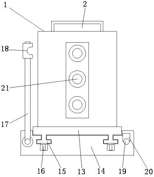
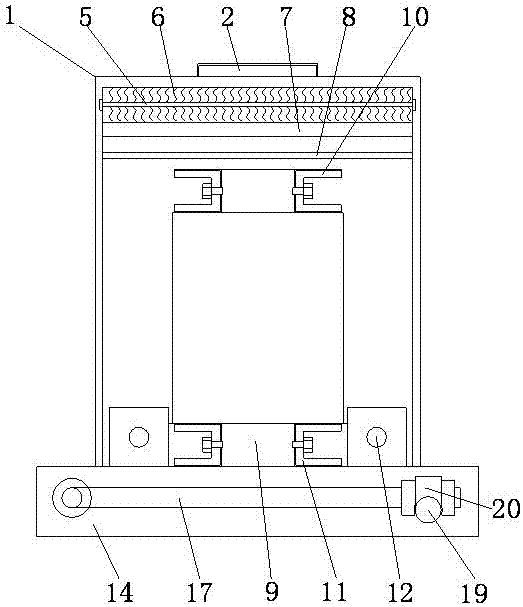
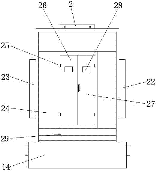
[0022] see Figure 1~4 , in an embodiment of the present invention, a dry-type transformer protection device includes a transformer box 1, the top of the transformer box 1 is provided with an air inlet frame 2, and the inner wall of the air inlet frame 2 is provided with a fan drive shaft 3 connected to the drive motor , the fan drive shaft 3 is provided with fan blades 4, the transformer box 1 is provided with a dust removal shaft 5 connected to the motor, th...


PUM


Abstract

The invention discloses a dry type transformer protection apparatus. The dry type transformer protection apparatus comprises a transformer box; a dust removal shaft connected with a motor is arranged in the transformer box; the transformer body comprises an iron core, clamps and a coil winding; a base is arranged on the lower part of the transformer box; a supporting base is arranged on the lower part of the base; a T-shaped sliding groove is formed in the supporting base; rolling wheel grooves are formed in the lower part of the T-shaped sliding groove; fixed frames are arranged on the two sides of the transformer box; wiring terminals are arranged in the fixed frames; a door plate is arranged on the front side of the transformer box; the door plate comprises a left door plate and a right door plate; and an air outlet is formed in the lower part of the door plate. The invention also discloses a use method of the dry type transformer protection apparatus. The dry type transformer protection apparatus is small in occupied area, convenient to move and transport, and low in production cost; the interior of the transformer is in air circulation to perform heat dissipation in time, so that burn down of the dry type transformer by a high temperature can be prevented effectively and the service life of the transformer is prolonged; and in addition, the dry type transformer protection apparatus has convenience in checking and overhaul and high practical value.

Description

[0001] This application is a divisional application of an invention patent application named: A dry-type transformer protection device, the application date is: December 12, 2016, and the application number is: 201611136511.1. technical field [0002] The invention relates to the technical field of a transformer protective shell, in particular to a dry-type transformer protective device and a use method thereof. Background technique [0003] Transformer protection device is a high-tech product of power automation integrating protection, monitoring, control, communication and other functions. It is an ideal electrical unit that constitutes an intelligent switch cabinet. The product has a built-in protection library consisting of more than 20 standard protection programs, and has a complete and powerful acquisition function for the voltage and current analog and switch values ​​of primary equipment (the current measurement is realized through the protection CT). [0004] The C...

Claims


Application Information

Patent Timeline
Patent Type & Authority Applications(China)
IPC IPC(8): H01F27/02H01F27/06H01F27/30H01F27/08B01D50/00
CPCB01D50/00H01F27/02H01F27/025H01F27/06H01F27/085H01F27/30H01F27/306
Inventor 沈小红
Owner 江苏国鑫电气科技有限公司
Why Eureka
Try Eureka