
Rapid assembly system

An assembly system, fast technology, used in metal processing equipment, metal processing machine parts, clamps, etc., can solve assembly problems, no temperature stability, etc.

Active Publication Date: 2017-12-01
克里斯托弗布瓦特
View PDF8 Cites 1 Cited by
  • Summary
  • Abstract
  • Description
  • Claims
  • Application Information

AI Technical Summary

Problems solved by technology

[0004] This system has the disadvantage of providing a large statically indeterminate position, which can lead to assembly problems, especially in environments without temperature stability

Method used


Image

  • Rapid assembly system
  • Rapid assembly system
  • Rapid assembly system

Examples


Embodiment Construction

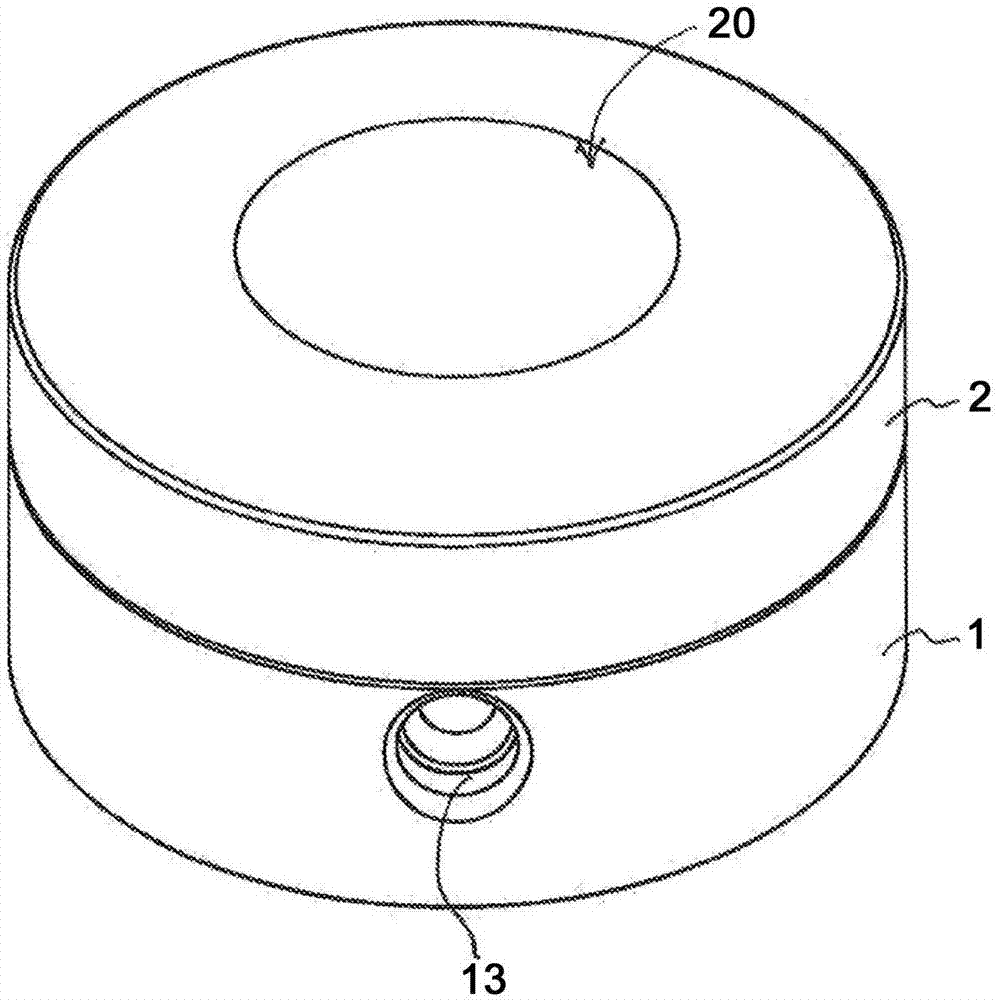
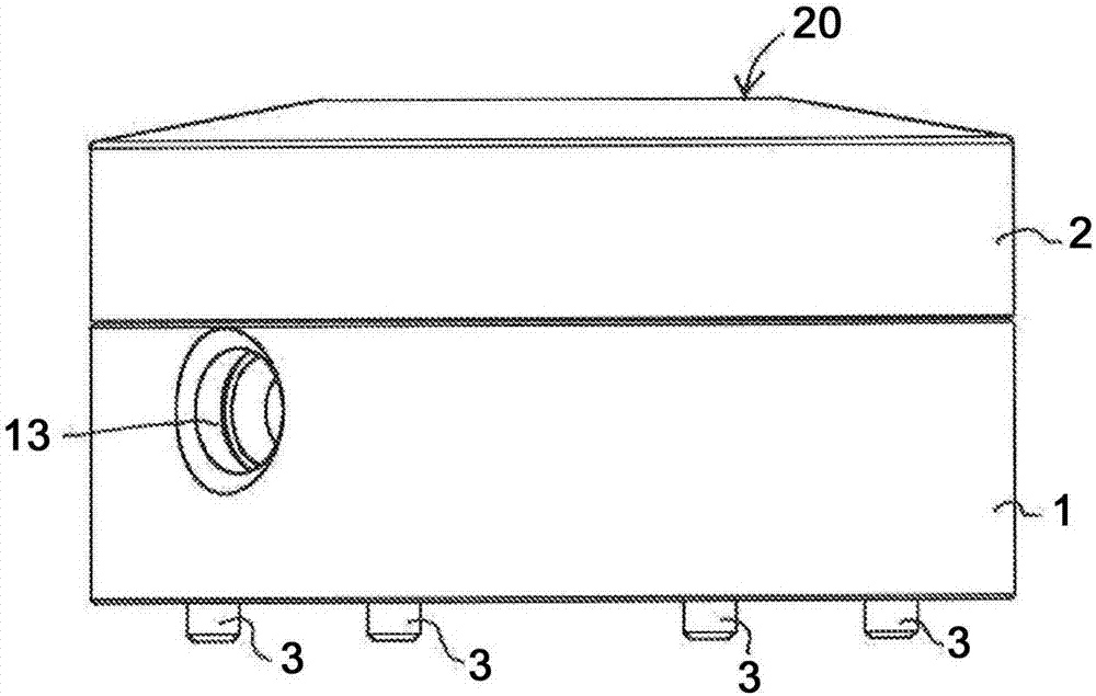
[0035] According to the first embodiment of the present invention, in figure 1 and figure 2 A quick assembly system comprising a mount 1 and a plate 2 removably fitted on the mount 1 is shown in . They have a cylindrical shape of substantially the same diameter. The upper surface 20 of the plate 2 is intended to receive a part (not shown) to be machined. The mount 1 is designed to be assembled on the table or spindle of a machine tool (not shown, such as a machining center or lathe). The screw 3 and the mounting 1 are shown and are designed to be attached to a machine tool.

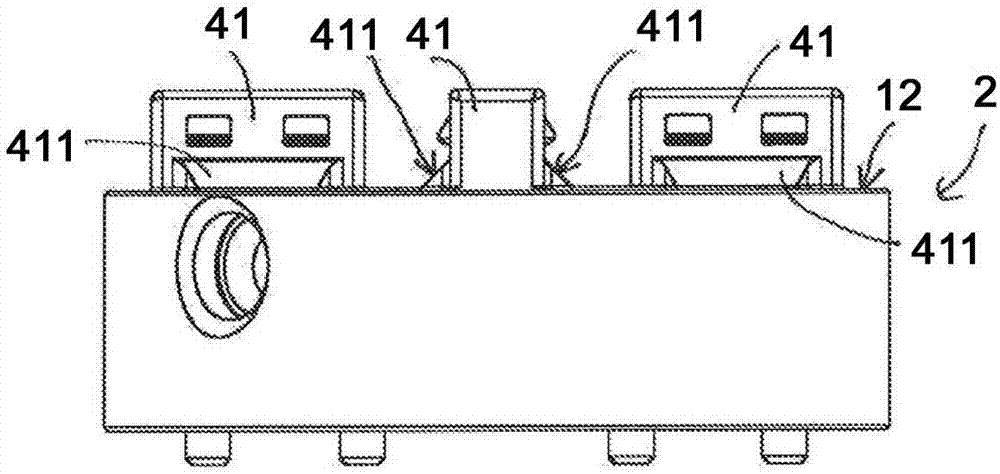
[0036]The assembly system comprises four connection devices 4 between the plate 2 and the mount 1 . Each connection device 4 comprises a tooth portion 41 attached to the mount 1 and a groove portion 42 provided in the plate 2 . Each tooth 41 comprises a pair of tooth engaging surfaces 411 arranged in a V shape, the theoretical intersection section of which extends in the direction of the tooth. The...


PUM


Abstract

A rapid assembly system comprises a mounting (1) and a plate (2) removably mounted onto the mounting (1). The system comprises connection devices (4) between the plate (2) and the mounting (1). Each device also comprises: - a clamping means (5) for holding the plate (2) against the mounting (1); - a tooth (41) comprising a pair of tooth engagement surfaces (411) arranged in a v-shape, the theoretical intersection of which extends in a tooth direction; and - a groove (42) comprising a pair of groove engagement surfaces (421) for engaging the tooth engagement surfaces (411).

Description

technical field [0001] The invention relates to a quick assembly system in the industrial field, such as a quick assembly system for a fixing device. The system includes a mount capable of removably receiving the board. Background technique [0002] In the field of machining it is known to provide a plate on which the part to be machined is attached. The plate itself will then be flanged to the table or spindle of the machining center for machining operations. The advantage is that parts can be interchanged very quickly, which enables a high productivity of the machining center. The parts are assembled to the board in a hidden time outside of the machining center. This solution also makes it possible to transfer the part to be machined between the different stations, without disassembling the part relative to the plate, and thus with respect to its frame of reference. Therefore, its high precision is ensured between transfers to different stations. [0003] Document DE ...

Claims


Application Information

Patent Timeline
Patent Type & Authority Applications(China)
IPC IPC(8): B23Q1/00
CPCB23Q1/0081B25B5/02B25B5/061B25B5/145
Inventor 克里斯托弗·布瓦特
Owner 克里斯托弗布瓦特
Learn More