Graphite viscosity regulating device for printing

A viscosity and graphite technology, applied in the field of graphite viscosity modulation devices for printing, can solve the problems of insufficient mixing of graphite and viscosity regulating powder, low efficiency of manual handling of viscosity regulating powder, etc.

Inactive Publication Date: 2017-12-05
高文扣
View PDF7 Cites 1 Cited by
  • Summary
  • Abstract
  • Description
  • Claims
  • Application Information

AI Technical Summary

Problems solved by technology

[0006] In order to overcome the shortcomings of low efficiency of manual handling of viscosity regulating powder and insufficient mixing of graphite and viscosity regulating powder in the prior art, the technical

Method used


Image

  • Graphite viscosity regulating device for printing
  • Graphite viscosity regulating device for printing
  • Graphite viscosity regulating device for printing

Examples


Embodiment 1

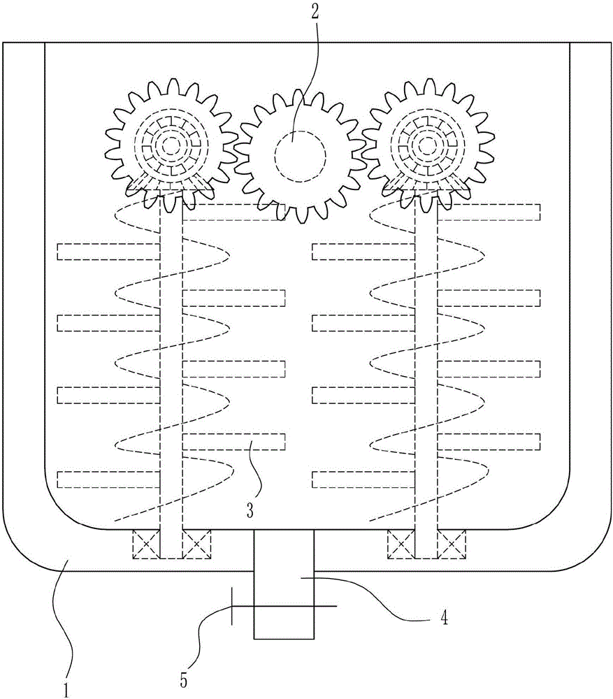
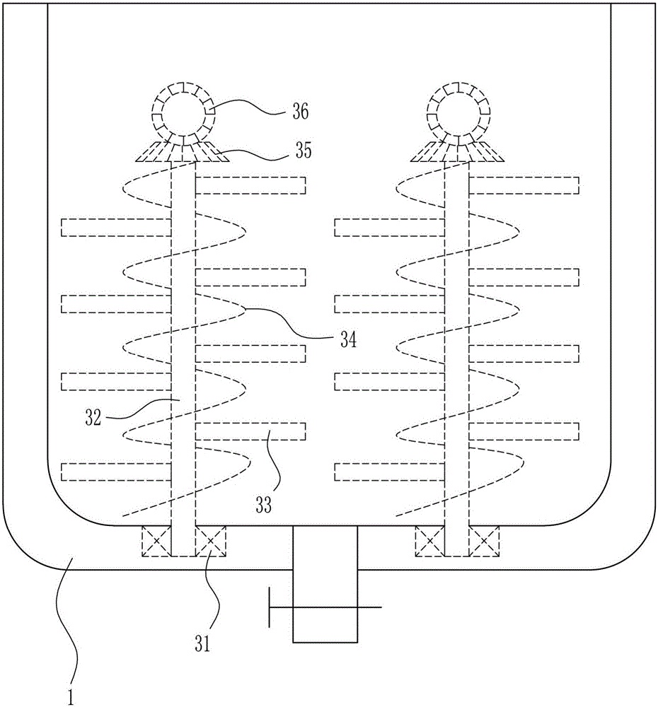
[0030] A graphite viscosity modulation device for printing, such as Figure 1-5 As shown, it includes a stirring box 1, a driving mechanism 2, a stirring mechanism 3, a discharge pipe 4 and a valve 5. The upper part of the stirring box 1 is connected with a driving mechanism 2, and the stirring box 1 is connected with a stirring mechanism 3. The bottom of the stirring box 1 A discharge pipe 4 is connected in the middle, and a valve 5 is arranged on the discharge pipe 4 .

Embodiment 2

[0032] A graphite viscosity modulation device for printing, such as Figure 1-5 As shown, it includes a stirring box 1, a driving mechanism 2, a stirring mechanism 3, a discharge pipe 4 and a valve 5. The upper part of the stirring box 1 is connected with a driving mechanism 2, and the stirring box 1 is connected with a stirring mechanism 3. The bottom of the stirring box 1 A discharge pipe 4 is connected in the middle, and a valve 5 is arranged on the discharge pipe 4 .

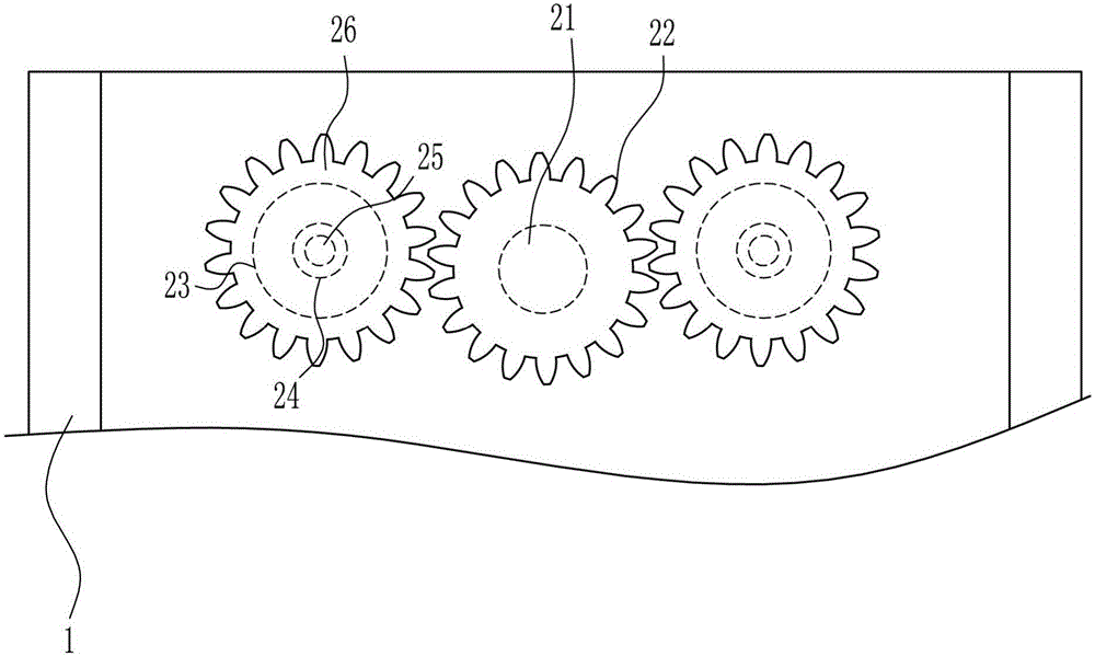
[0033] The driving mechanism 2 includes a motor 21, a first gear 22, a first bearing seat 23, a sealing ring 24, a first rotating rod 25 and a second gear 26, and a motor 21 is connected in the middle of the outer front wall of the mixing box 1, and the output of the motor 21 The front side of the shaft is connected with a first gear 22, the left and right sides of the outer front wall of the mixing box 1 are connected with a sealing ring 24, the left and right sides of the outer front wall of the mixing box...

Embodiment 3

[0035] A graphite viscosity modulation device for printing, such as Figure 1-5 As shown, it includes a stirring box 1, a driving mechanism 2, a stirring mechanism 3, a discharge pipe 4 and a valve 5. The upper part of the stirring box 1 is connected with a driving mechanism 2, and the stirring box 1 is connected with a stirring mechanism 3. The bottom of the stirring box 1 A discharge pipe 4 is connected in the middle, and a valve 5 is arranged on the discharge pipe 4 .

[0036] The driving mechanism 2 includes a motor 21, a first gear 22, a first bearing seat 23, a sealing ring 24, a first rotating rod 25 and a second gear 26, and a motor 21 is connected in the middle of the outer front wall of the mixing box 1, and the output of the motor 21 The front side of the shaft is connected with a first gear 22, the left and right sides of the outer front wall of the mixing box 1 are connected with a sealing ring 24, the left and right sides of the outer front wall of the mixing box 1...


PUM


Abstract

The invention relates to a graphite viscosity regulating device, and particularly relates to a graphite viscosity regulating device for printing. The invention aims to solve a technical problem by providing the graphite viscosity regulating device for the printing, wherein the device has a viscosity adjusting powder and can fully mix graphite and the viscosity adjusting powder. In order to solve the above problem, the invention provides such a graphite viscosity regulating device for the printing: the device comprises a stirring box and the like; and the upper part of the stirring box is connected with driving mechanisms, the interior of the stirring box is connected with stirring mechanisms, the middle of the bottom of the stirring box is connected with a material outlet pipe, and the material outlet pipe is provided with a valve. According to the invention, a placing box is arranged in the device, thus a proper amount of the viscosity adjusting powder can be conveniently added into the stirring box to adjust graphite viscosity; and a rubber clamping rod, a second slide rail and a second slide block are arranged in the device, thus a baffle can be fixed, and when the graphite and the viscosity adjusting powder are mixed and stirred, a condition that the baffle is loose and causes falling of excessive viscosity adjusting powder into the stirring box and further influence on graphite viscosity regulating is prevented.

Description

technical field [0001] The invention relates to a graphite viscosity modulation device, in particular to a graphite viscosity modulation device for printing. Background technique [0002] Printing (that is, graphic communication) is to transfer the ink to the surface of paper, fabric, plastic, leather and other materials through the processes of plate making, ink application, and pressure on originals such as text, pictures, photos, and anti-counterfeiting, and copy the contents of the originals in batches. Technology. [0003] The graphite needs to have sufficient viscosity during the printing process, so the viscosity of the graphite needs to be adjusted before printing. The existing modulation method is generally to manually take out the viscosity adjustment powder at a specific place, and then add the viscosity adjustment powder to the modulator for mixing , In this way, not only the work efficiency is low, but also the mixing of graphite and viscosity adjusting powder ...

Claims


Application Information

Patent Timeline
IPC IPC(8): B01F7/16B01F15/00
CPCB01F27/074B01F27/1921B01F27/2322B01F27/85B01F35/30B01F2101/35
Inventor 高文扣
Owner 高文扣
Why Eureka
Try Eureka