Steering drive shaft connection structure

A technology of steering transmission shaft and connecting structure, which is applied in steering column, steering control mounted on the vehicle, etc., can solve the problems affecting the driver's operating comfort, and achieve the effects of improving operating comfort, convenient assembly and reducing noise.

Active Publication Date: 2019-05-07
ANHUI JIANGHUAI AUTOMOBILE GRP CORP LTD
View PDF7 Cites 0 Cited by
  • Summary
  • Abstract
  • Description
  • Claims
  • Application Information

AI Technical Summary

Problems solved by technology

[0005] In order to solve the problem that the existing two transmission shafts are rigidly connected together, since the steering transmission shaft is rigidly connected, the vibration and twist generated during the vehicle running process are transmitted to the steering control system, so that the torsional vibration of the steering shaft is directly transmitted to the steering wheel. Issues that will affect the driver's operating comfort

Method used


Image

  • Steering drive shaft connection structure
  • Steering drive shaft connection structure
  • Steering drive shaft connection structure

Examples


Embodiment Construction

[0021] In order to enable those skilled in the art to better understand the technical solutions of the present invention, the present invention will be further described in detail below in conjunction with the accompanying drawings.

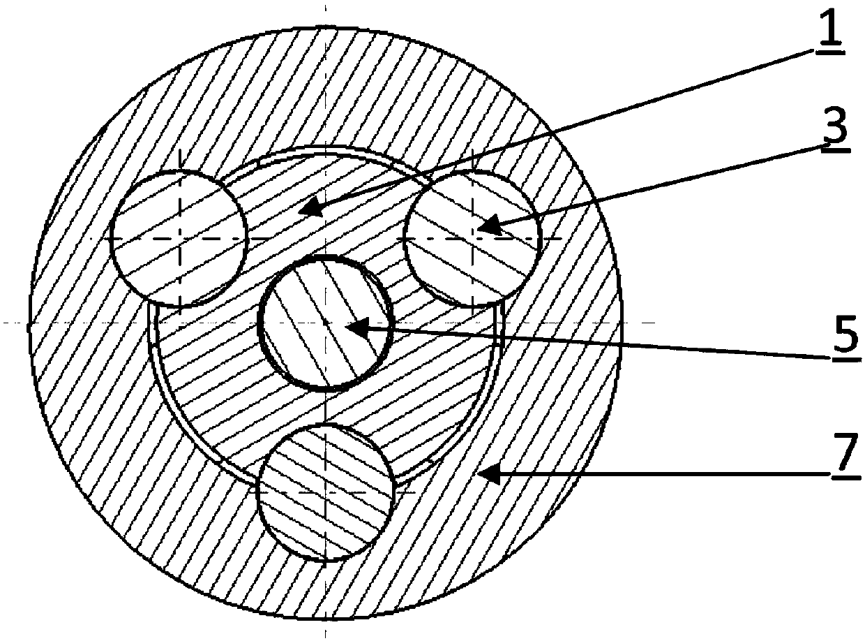
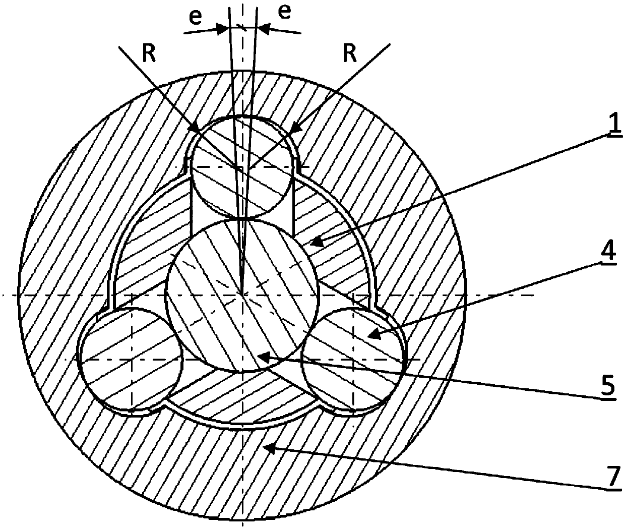
[0022] see Figure 1 to Figure 4 As shown, it is a steering transmission shaft connection structure provided by the embodiment of the present invention, and its purpose is to flexibly connect the upper and lower two transmission shafts. Wherein, the lower transmission shaft 1 is connected to the steering gear through a universal joint, and the upper transmission shaft 7 is connected to the steering wheel through a universal joint.

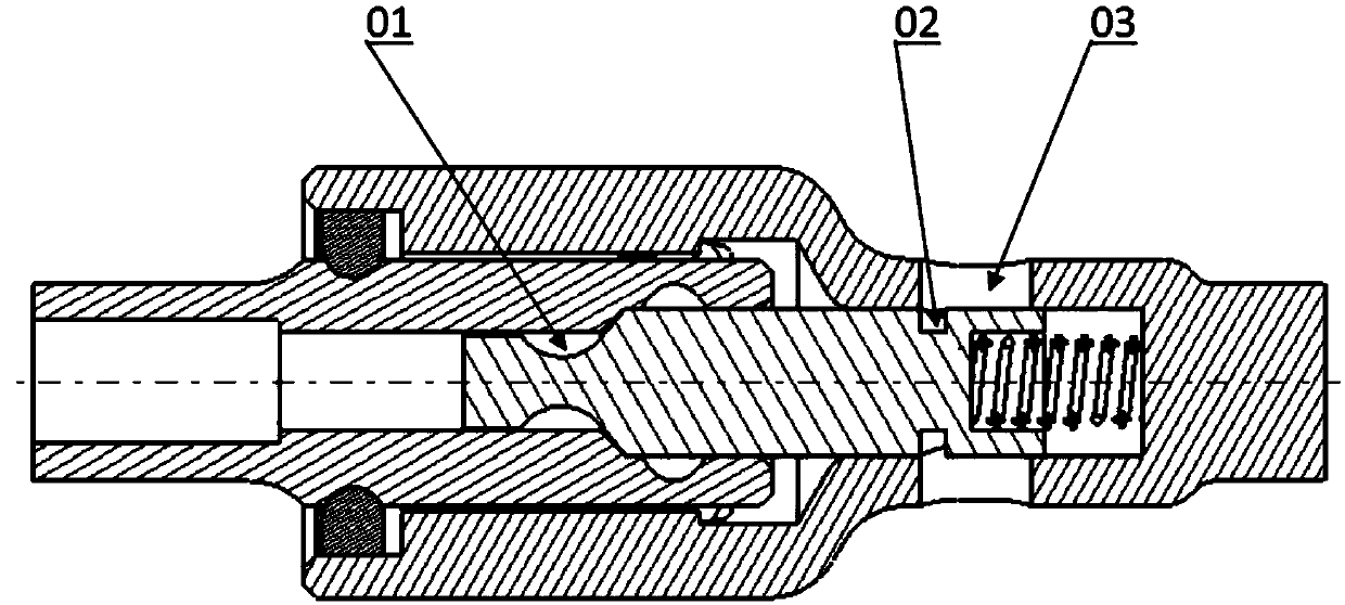
[0023] Specifically, it includes: a self-locking pin 5 , the self-locking pin 5 is provided with a plurality of circular grooves 01 in the circumferential direction, and the circular grooves 01 are used to accommodate the self-locking steel ball 4 .

[0024] The upper transmission shaft 7 has a connecting sleeve at t...


PUM


Abstract

The invention discloses a steering transmission shaft connecting structure. The structure comprises a self-lock pin, an upper transmission shaft, a lower transmission shaft, a self-lock spring and self-lock steel balls; multiple circular grooves are formed in the self-lock pin in the periphery direction, and the end of the upper transmission shaft is provided with a connecting sleeve; the lower transmission shaft is inserted in the connecting sleeve; the self-lock pin is slidably installed at the end of the lower transmission shaft in the axial direction; multiple locating holes are formed in the outer wall of the end of the lower transmission shaft in the periphery direction; multiple locking grooves corresponding to the locating holes are formed in the inner wall of the connecting sleeve; the self-lock spring is arranged between the self-lock pin and the upper transmission shaft in the axial direction and used for driving the locking grooves and the locating holes to separate axially; the self-lock steel balls are located in the circular grooves and the locating holes when not locked tightly; when the self-lock steel balls are automatically locked, the locking grooves move axially, and the self-lock steel balls move vertically, are separated from the circular grooves and prop up between the outer wall of the self-lock pin and the locking grooves. Through the steering transmission shaft connecting structure, the steering torque can be reliably transmitted, and meanwhile the situation that a car is influenced by all kinds of action force during driving can be eliminated.

Description

technical field [0001] The invention relates to the field of connection of steering transmission shafts, in particular to a connection structure of steering transmission shafts. Background technique [0002] The steering shaft is the transmission part that connects the steering wheel and the steering gear, and is an important part of the steering system of the car. The design of the steering shaft, on the one hand, must ensure that it can transmit torque reliably; Vibrations are more intense when driving forward and at the beginning of a steering movement, which affects the driver's operating comfort when it is transmitted to the steering wheel. [0003] At present, the structure of the flexible coupling of the automobile steering transmission shaft is complex and the cost is high. In order to control the cost of light passenger products, the steering system connects the steering wheel and the steering gear through the shaft and the universal joint, so that the driver's ste...

Claims


Application Information

Patent Timeline
Patent Type & Authority Patents(China)
IPC IPC(8): B62D1/20
CPCB62D1/20
Inventor 孙光仙陈正江姜超左印波
Owner ANHUI JIANGHUAI AUTOMOBILE GRP CORP LTD
Why Eureka
Try Eureka