Outlet structure of pipeline of non-excavation type comprehensive pipe rack and method thereof

A comprehensive pipe gallery and non-excavation technology, applied in underwater structures, infrastructure engineering, water conservancy projects, etc., can solve problems such as high cost, large distance between working wells, and difficult to meet pipeline requirements, and improve construction efficiency , The effect of facilitating construction

Inactive Publication Date: 2017-12-05
GUANGZHOU METRO DESIGN & RES INST
View PDF7 Cites 7 Cited by
  • Summary
  • Abstract
  • Description
  • Claims
  • Application Information

AI Technical Summary

Problems solved by technology

Due to the limitation of construction conditions, the setting of the working well of the non-excavation integrated pipe gallery needs to consider many factors such as the construction period of the pipe gallery tunnel, construction difficulty, implementation feasibility, and surrounding pipeline requirements, and the distance between the working wells is generally large. The location and method of outgoing lines are not flexible. Different types of pipelines can only be connected to external users at the same location, which requires a long distance and high cost, and it is difficult to meet the demand for new pipelines in the later period.

Method used


Image

  • Outlet structure of pipeline of non-excavation type comprehensive pipe rack and method thereof
  • Outlet structure of pipeline of non-excavation type comprehensive pipe rack and method thereof
  • Outlet structure of pipeline of non-excavation type comprehensive pipe rack and method thereof

Examples


Embodiment 1

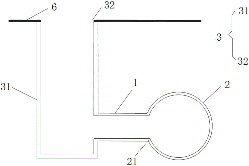
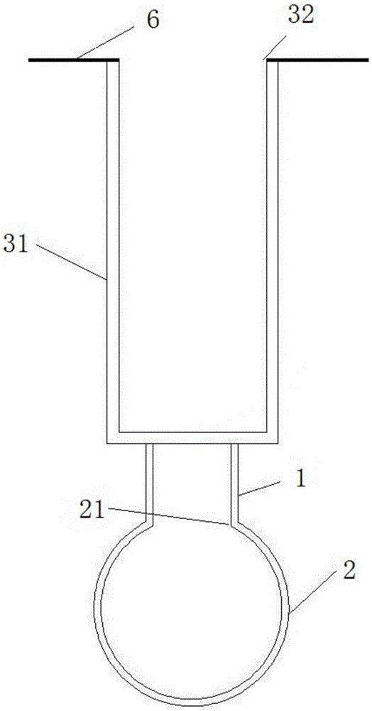
[0038] like figure 1 , 2 As shown in and 7, the outlet shaft is a shaft 3, the shaft 3 includes a shaft body 31, the first opening is a shaft lock 32 communicating with the ground 6, and the shaft lock 32 is connected to the shaft shaft The upper end of the body 31 is connected. When the comprehensive pipe gallery tunnel 2 is first constructed and penetrated, the second opening is opened on the side: the wellhead is excavated from the construction ground 6, and the shaft lock is constructed, and then excavated downwards, and the construction is carried out in sections along with the excavation. Initial support until the bottom cover; open the second opening on the top: to the top of the comprehensive utility tunnel 2 and reserve a certain safety distance; further, the shaft 3 also includes a transverse passage connected with the cable trench, and the transverse The passage is arranged at the upper end of the shaft shaft 31, and the transverse passage communicates with the sha...

Embodiment 2

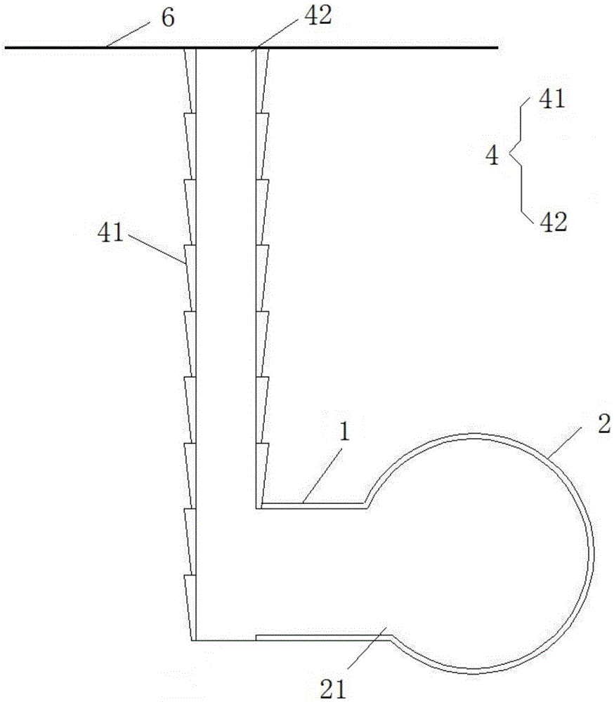
[0040] like image 3 , 4As shown in and 7, the outlet well is an artificial hole-digging pile 4, and the artificial hole-digging pile 4 includes a plurality of segmental reinforced concrete retaining walls 41, and the first opening is a transitional retaining wall 42 communicated with the ground 6, and a plurality of The segmental reinforced concrete retaining wall 41 is connected up and down sequentially, and the transitional retaining wall 42 is connected with the upper end of the segmental reinforced concrete retaining wall 41 at the top. When the comprehensive pipe gallery tunnel 2 is first constructed and penetrated, a second opening 43 is opened on the side: Excavate the wellhead from the construction ground 6, construct the shaft lock, excavate and sink in sections to form the retaining wall until the bottom seal; open the second opening at the top: excavate in stages and construct the retaining wall to the top of the comprehensive pipe gallery tunnel 2 and A certain s...

Embodiment 3

[0042] like Figures 5 to 7 As shown, the outlet well is an open cut working well 5, the open cut working well 5 includes a working well shaft 51, the first opening is a working well connecting section structure 52 communicating with the ground 6, and the working well The connecting section structure 52 communicates with the upper end of the working well shaft 51. After the comprehensive pipe gallery tunnel 2 is first constructed and penetrated, a second opening is opened on the side: the working well connecting section structure 52 is constructed on the ground 6, and the main structure or Directly adopt the caisson form; open the second opening at the top: to the top of the comprehensive utility tunnel 2 and reserve a certain safety distance; further, the open cut work shaft 5 also includes a transverse channel connected with the cable trench, so The transverse channel is arranged on the upper end of the working well body 51, and the transverse channel communicates with the w...


PUM


Abstract

The invention provides an outlet structure of a pipeline of a non-excavation type comprehensive pipe rack. The outlet structure comprises an outlet well, a connecting channel and a comprehensive pipe rack tunnel. The outlet well comprises a first opening and a second opening. The first opening is formed in the upper end of the outlet well and communicates with the ground, and the second opening is formed in the outlet well; a third opening is formed in the comprehensive pipe rack tunnel; one end of the connecting channel communicates with the second opening while the other end of the connecting channel communicates with the third opening, and the outlet well, the connecting channel and the comprehensive pipe rack tunnel successively communicate to form a through outlet channel. The outlet structure of the pipeline of the non-excavation type comprehensive pipe rack provided by the invention solves the problem of pipeline outlet of a built tunnel of the non-excavation type comprehensive pipe rack and determines the pipeline outlet mode.

Description

technical field [0001] The invention relates to the field of municipal engineering, in particular to a pipeline outlet structure of a non-excavation comprehensive utility gallery and a method thereof. Background technique [0002] The pipeline outlet mode of the comprehensive utility gallery is the way that the pipeline in the utility gallery is connected to the outside of the cabin, connected with the external pipeline, and finally connected to the outside user. The pipeline outlet of the excavated pipe gallery is usually connected to the external pipeline by simultaneously constructing the outlet shaft and reserving the outlet cabin at the same time as the pipe gallery is constructed. Due to the good construction conditions and shallow buried depth of the excavated pipe gallery, there are fewer restrictions on the setting of outlet wells and reserved outlet cabins. Due to the complex ground conditions and deep burial depth of the trenchless pipe gallery, there may be many...

Claims


Application Information

Patent Timeline
Patent Type & Authority Applications(China)
IPC IPC(8): E02D29/045E02D29/12
CPCE02D29/10E02D29/12
Inventor 柳宪东史海欧翟利华刘鑫解丰波龙丽姮李林林王晓娜孟子雄张晓利
Owner GUANGZHOU METRO DESIGN & RES INST
Why Eureka
Try Eureka