Power distribution cabinet internal dedusting device

A technology for dust removal devices and power distribution cabinets, which can be applied to substation/distribution device enclosures, smoke removal, substation/switch layout details, etc., and can solve the problems of time-consuming and laborious, low dust removal efficiency

Inactive Publication Date: 2017-12-05
邵林芳
View PDF3 Cites 12 Cited by
  • Summary
  • Abstract
  • Description
  • Claims
  • Application Information

AI Technical Summary

Problems solved by technology

[0005] In order to overcome the shortcomings of time-consuming and labor-intensive and low dust removal efficiency for manual dust removal inside the power distribution cabinet, the technical problem to be solved by the invention is to provide a time-saving and labor-saving device that can improve dust removal efficiency and is easy to use and easy to operate. Simple dust removal device inside the power distribution cabinet

Method used


Image

  • Power distribution cabinet internal dedusting device
  • Power distribution cabinet internal dedusting device
  • Power distribution cabinet internal dedusting device

Examples


Embodiment 1

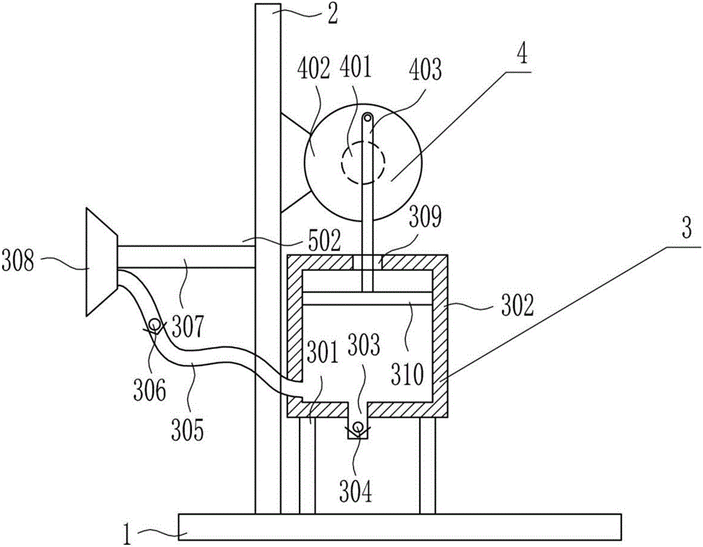
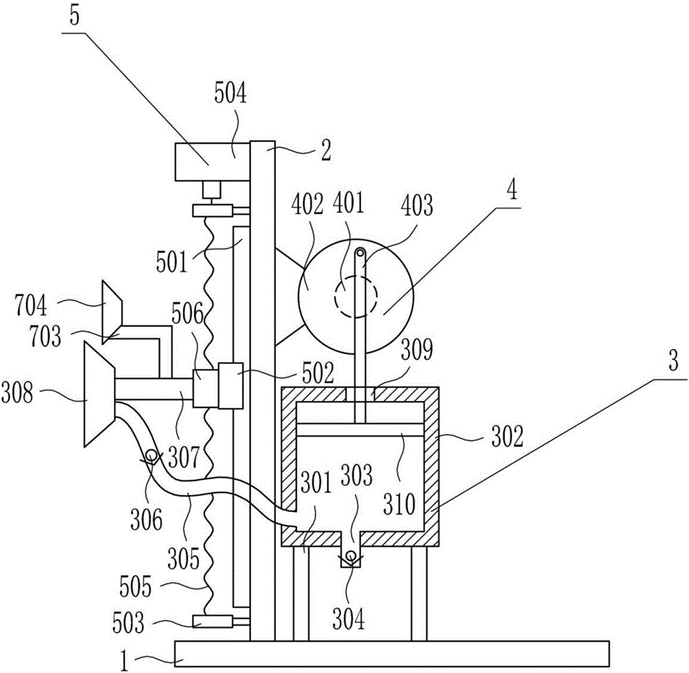
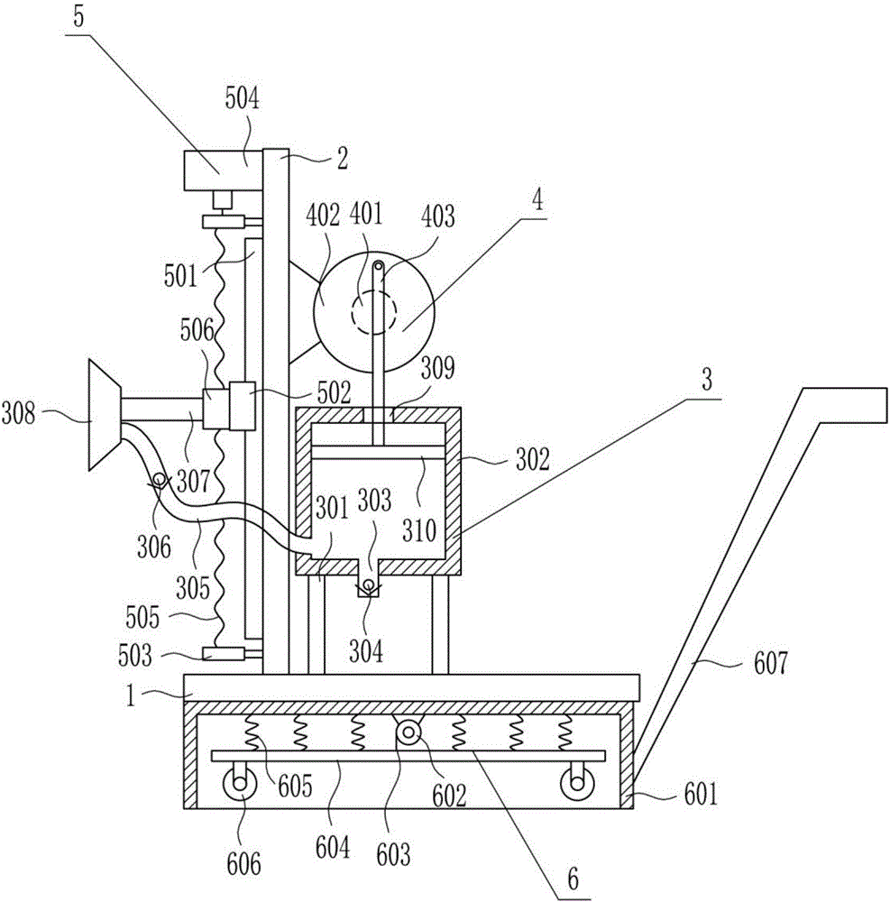
[0035] A dust removal device inside a power distribution cabinet, such as Figure 1-5 As shown, it includes a base plate 1, a support plate 2, a dust removal device 3 and a driving device 4. The left side of the top of the base plate 1 is vertically provided with a support plate 2, and the top of the base plate 1 on the right side of the support plate 2 is provided with a dust removal device 3. The dust removal part of the device 3 is located on the left side of the support plate 2, and the upper right side of the support plate 2 is provided with a driving device 4.

Embodiment 2

[0037] A dust removal device inside a power distribution cabinet, such as Figure 1-5 As shown, it includes a base plate 1, a support plate 2, a dust removal device 3 and a driving device 4. The left side of the top of the base plate 1 is vertically provided with a support plate 2, and the top of the base plate 1 on the right side of the support plate 2 is provided with a dust removal device 3. The dust removal part of the device 3 is located on the left side of the support plate 2, and the upper right side of the support plate 2 is provided with a driving device 4.

[0038] The dust removal device 3 includes a support rod 301, a compression box 302, an air inlet pipe 303, a first one-way valve 304, an air outlet pipe 305, a second one-way valve 306, a cross bar 307, an air spray nozzle 308 and a piston 310, and the support rod 301 is designed There are two, two poles 301 are left and right symmetrical, the bottom of the poles 301 is connected with the top of the bottom plate ...

Embodiment 3

[0040] A dust removal device inside a power distribution cabinet, such as Figure 1-5 As shown, it includes a base plate 1, a support plate 2, a dust removal device 3 and a driving device 4. The left side of the top of the base plate 1 is vertically provided with a support plate 2, and the top of the base plate 1 on the right side of the support plate 2 is provided with a dust removal device 3. The dust removal part of the device 3 is located on the left side of the support plate 2, and the upper right side of the support plate 2 is provided with a driving device 4.

[0041] The dust removal device 3 includes a support rod 301, a compression box 302, an air inlet pipe 303, a first one-way valve 304, an air outlet pipe 305, a second one-way valve 306, a cross bar 307, an air spray nozzle 308 and a piston 310, and the support rod 301 is designed There are two, two poles 301 are left and right symmetrical, the bottom of the poles 301 is connected with the top of the bottom plate ...


PUM


Abstract

The invention relates to power distribution cabinet dedusting devices, particularly to a power distribution cabinet internal dedusting device. The power distribution cabinet internal dedusting device is time-saving, labor-saving, capable of improving the dedusting efficiency, convenient to use and simple in operation. The power distribution cabinet internal dedusting device comprises a bottom plate and the like; the left of the top of the bottom plate is vertically provided with a support plate; the part of the top of the bottom plate on the left of the support plate is provided with a dedusting device body, the dedusting unit of the dedusting device body is arranged on the left of the support plate, and the upper portion of the right surface of the support plate is provided with a driving device. According to the power distribution cabinet internal dedusting device, the driving device can drive the dedusting device body to rapidly dedust the inside of a power distribution cabinet, and a dust suction device can suck away dust. Therefore, the power distribution cabinet internal dedusting device can achieve the effects of being time-saving, labor-saving, capable of improving the dedusting efficiency, convenient to use and simple in operation.

Description

technical field [0001] The invention relates to a dust removal device for a power distribution cabinet, in particular to an internal dust removal device for a power distribution cabinet. Background technique [0002] The power distribution cabinet (box) is divided into power distribution cabinet (box), lighting distribution cabinet (box), metering cabinet (box), and is the final equipment of the power distribution system. The power distribution cabinet is a general term for the motor control center. The power distribution cabinet is used in the occasions where the load is relatively scattered and there are few circuits; the motor control center is used in the occasions where the load is concentrated and there are many circuits. They distribute the electric energy of a certain circuit of the upper-level power distribution equipment to the nearest load. This level of equipment shall provide protection, monitoring and control of the load. [0003] After the long-term operati...

Claims


Application Information

Patent Timeline
Patent Type & Authority Applications(China)
IPC IPC(8): H02B1/30H02B1/28B08B5/02B08B15/04
CPCH02B1/306B08B5/02B08B15/04H02B1/28
Inventor 邵林芳
Owner 邵林芳
Why Eureka
Try Eureka