Novel medical peritoneal drainage tube and use method thereof

A drainage tube and abdominal cavity technology, applied in the field of new medical abdominal drainage tube, can solve the problems of inability to flush, single function, dilution, etc., and achieve the effect of facilitating tissue repair, cleaning the environment, and preventing the spread of infection

Inactive Publication Date: 2017-12-08
南宁腾科宝迪生物科技有限公司 +1
View PDF13 Cites 5 Cited by
  • Summary
  • Abstract
  • Description
  • Claims
  • Application Information

AI Technical Summary

Problems solved by technology

[0003] At present, most of the various drainage tubes commonly used in clinical practice have single functions, can only drain, and cannot be washed, and there are only a few drainage tubes that can be washed, but their design is unreasonable. The water pipe is set in the suction pipe, and the water flow cannot be released into the human organs and tissues outside the pipe, resulting in a dead cycle in which the water is sucked out in the pipe after entering the water, which cannot play the role of washing the human organs and tissues
Chinese patent (application number: 201520472866.2, publication date: January 13, 2016) discloses a medical flushing and drainage tube. The flushing and drainage tube provided by the patent is provided with an outer sleeve, an inner sleeve and two side tubes. Embedded inside the outer cannula, the two side tubes are set outside the inner cannula. When in use, the space between the second side tube and the first side tube may be blocked by human tissue, and at the same time, there is no way to connect the tissues in the wound or the body cavity. The pus, blood, and fluid accumulated in the wound are diluted and completely drained to the outside of the human body, which can easily cause wound infection

Method used


Image

  • Novel medical peritoneal drainage tube and use method thereof
  • Novel medical peritoneal drainage tube and use method thereof
  • Novel medical peritoneal drainage tube and use method thereof

Examples


Embodiment Construction

[0045] In order to make the objectives, technical solutions, and advantages of the embodiments of the present invention clearer, the technical solutions in the embodiments of the present invention will be described clearly and completely in conjunction with the accompanying drawings in the embodiments of the present invention. Obviously, the described embodiments It is a part of the embodiments of the present invention, not all the embodiments. Based on the embodiments of the present invention, all other embodiments obtained by those of ordinary skill in the art without creative work shall fall within the protection scope of the present invention.

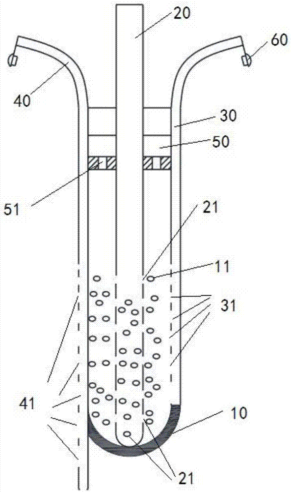
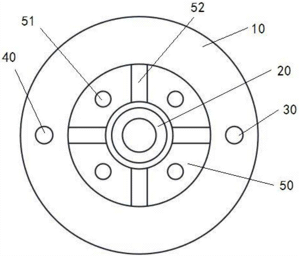
[0046] figure 1 It is a schematic diagram of the structure of the new medical abdominal drainage tube provided by the present invention, figure 2 It is the top view of the new medical abdominal drainage tube, such as figure 1 with figure 2 Shown: a new type of medical abdominal drainage tube, including a drainage tube 10, a negative ...


PUM


Abstract

The invention provides a novel medical peritoneal drainage tube and a use method thereof. The novel medical peritoneal drainage tube comprises a drainage tube, a negative pressure tube, a first side tube, a second side tube and a fixing loop, wherein multiple first through holes are formed in the side wall of the drainage tube; the negative pressure tube is fixed in the drainage tube through the fixing loop; a vent hole is formed in the fixing loop; the first side tube and the second side tube are both arranged on tube walls of the drainage tube; one end of the second side tube extends out of one end of the drainage tube. The novel medical peritoneal drainage tube can clean polluted tissue in the body cavity and drain polluted tissue fluids in the body cavity outside of the human body cavity through suction of the negative pressure tube. With the adoption of the novel medical peritoneal drainage tube, the polluted tissue fluids in the body cavity can be drained clean, the internal environment of the body cavity can be clean, inflammations are localized, tissue repair is facilitated, and postoperative infection diffusion and effects on wound healing can be prevented.

Description

Technical field [0001] The present invention relates to the field of medical devices, in particular to a new type of medical abdominal drainage tube and a method of use thereof. Background technique [0002] There are many types of surgical drainage tubes used clinically, some are used for catheterization, and some are used for wounds, chest cavity, brain cavity, gastrointestinal tract, biliary tract, etc. Surgical drainage is to guide the pus, blood, and fluid accumulated between human tissues or body cavities to the body to prevent the spread of postoperative infection and affect wound healing. [0003] At present, most of the various drainage tubes commonly used in clinical practice have a single function. They can only drain but cannot be flushed. There are only a small number of drainage tubes that can be flushed. However, their design is unreasonable. For example, the current clinical application of Kangli drainage tubes has advanced The water pipe is sheathed in the suction...

Claims


Application Information

Patent Timeline
Patent Type & Authority Applications(China)
IPC IPC(8): A61M1/00A61M3/02A61M25/14A61M25/00
CPCA61M3/0283A61M25/0021A61M25/0043A61M25/007A61M25/0026A61M2025/0019A61M2025/0037A61M2210/1021A61M1/83A61M1/84A61M1/772A61M1/85A61M2210/005A61M2210/1017
Inventor 郑清树
Owner 南宁腾科宝迪生物科技有限公司
Why Eureka
Try Eureka