A continuous flow reactor

A reactor and reaction tube technology, applied in the field of continuous flow reactors, can solve the problems of large reactor volume, poor turbulent flow effect, and low Reynolds coefficient, and achieve the effects of improving turbulent flow effect, simplifying installation and assembly, and improving reaction process.

Active Publication Date: 2018-11-02
SHANDONG NERVE PHARMA FLUID SYST CO LTD
View PDF4 Cites 12 Cited by
  • Summary
  • Abstract
  • Description
  • Claims
  • Application Information

AI Technical Summary

Problems solved by technology

[0003] The concentration and reaction rate of chemical reactants in the tubular reactor change with the length of the tube, so the tubular reactor needs to meet the tube length required by the chemical reaction, and the existing straight tube reactor or U-shaped tube reactor should be relatively Long tube length, the reactor volume is too large
In addition, the flow state of the reactants in the reaction tube will directly affect the heat transfer rate of the reaction and the uninterrupted mixing effect. The traditional straight tube reactor has poor turbulent flow effect of the reaction material and low Reynolds coefficient, which is not conducive to heat transfer and uninterrupted mixing effect.

Method used


Image

  • A continuous flow reactor
  • A continuous flow reactor
  • A continuous flow reactor

Examples


Embodiment 1

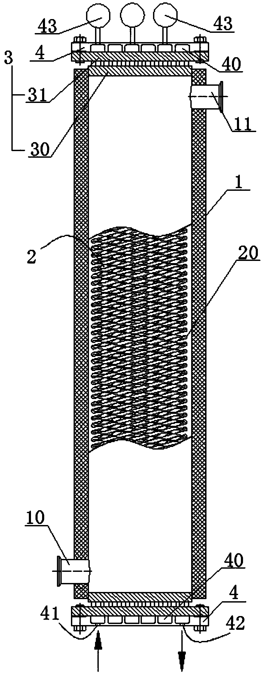
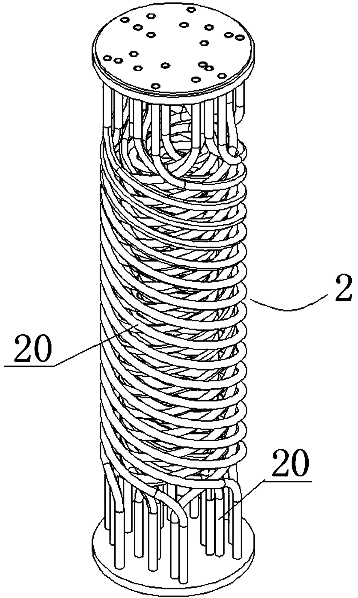
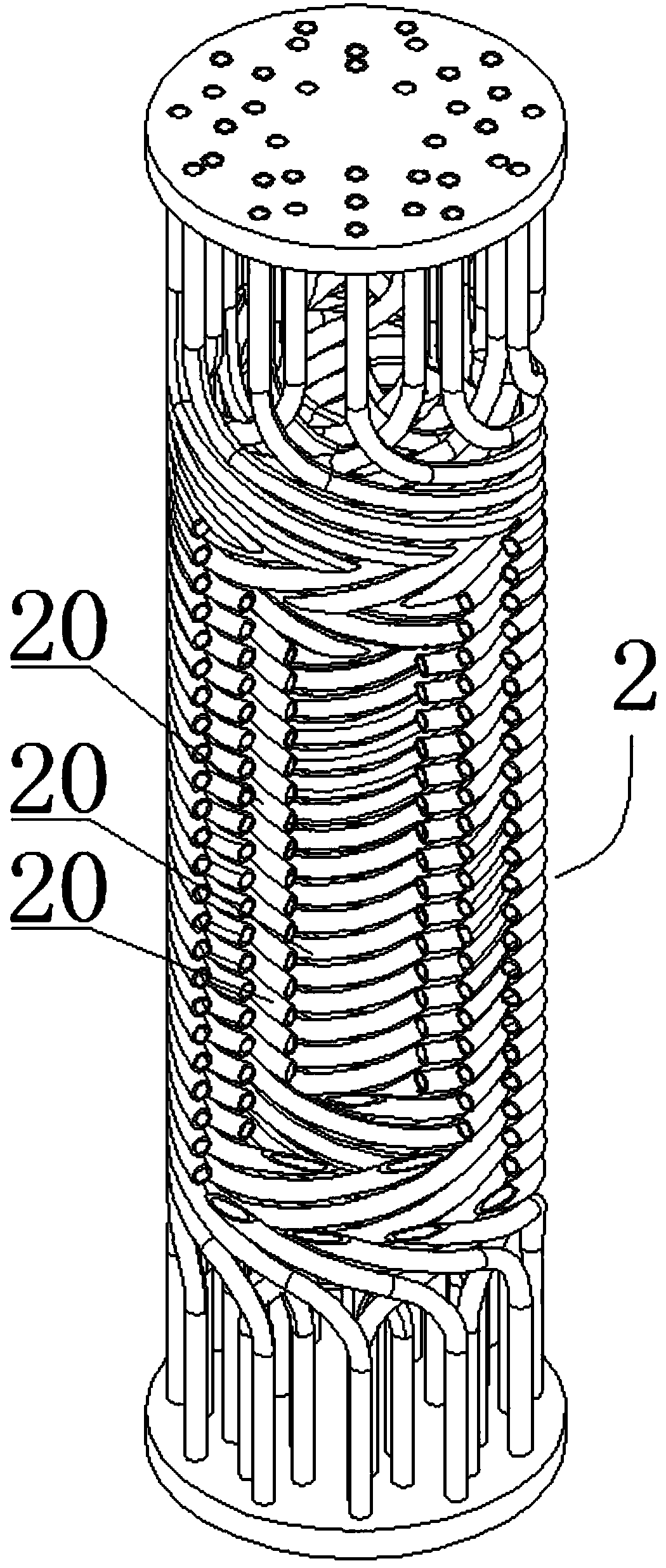
[0030] Such as Figure 1 to Figure 5 As shown, a continuous flow reactor of this embodiment is characterized in that it includes: a shell 1, the shell 1 is provided with a shell-side inlet 10 and a shell-side outlet 11 communicating with its inner cavity, the shell The shell side of 1 is used to circulate the heat transfer medium, so that the reactants in the tube side of the reaction tube 20 can maintain a suitable reaction temperature. The upper and lower ends of the shell 1 are connected with a tube plate 3 and a communication device. The interior of the reaction tube set 2 is arranged, and the reaction tube set 2 includes a plurality of reaction tubes 20, and the upper and lower ends of each reaction tube pass through and are fixedly connected to the tube plate 3, and all the reaction tubes 20 are sequentially passed through the communication device. Connected in series.

[0031] Such as Figure 4 with Figure 5 As shown, preferably, the communication device is a baffle...


PUM


Abstract

The invention relates to the technical field of chemical and pharmaceutical equipment, in particular to a continuous flow reactor. The continuous flow reactor comprises a shell, wherein a shell side inlet and a shell side outlet which are communicated with an inner cavity of the casing are arranged on the shell; each of the upper end and the lower end of the shell is connected with a tube plate and a communicating device, a reaction tube stack is arranged in the shell and comprises multiple reaction tubes, the upper end and the lower end of each reaction tube penetrate through and are fixedly connected on the tube plates, and all the reaction tubes are sequentially connected in series through the communicating devices. By comparison with a traditional reactor, the reaction process is greatly improved under the condition of the same volume, reactants have high reynolds numbers under the condition of a low flow speed, the turbulence effect is greatly improved, unintermittent mixing is performed during constant flowing reactions, states of reaction stages can be detected in real time, and mounting and assembly are simplified.

Description

technical field [0001] The invention relates to the technical field of chemical and pharmaceutical equipment, in particular to a continuous flow reactor. Background technique [0002] Reactor equipment commonly used in the field of chemical and pharmaceutical technology includes tubular reactors and tank reactors, etc. Among them, tank reactors are often equipped with stirring devices in the reactor for mixing liquid phase reactants. The conversion rate is low, and the energy consumption and pollution are serious. Due to the high requirements for the purity of products in the chemical and pharmaceutical fields, the commonly used reactor equipment is a continuous flow tube reactor. [0003] The concentration and reaction rate of chemical reactants in the tubular reactor change with the length of the tube, so the tubular reactor needs to meet the tube length required by the chemical reaction, and the existing straight tube reactor or U-shaped tube reactor should be relatively...

Claims


Application Information

Patent Timeline
Patent Type & Authority Patents(China)
IPC IPC(8): B01J19/24
CPCB01J19/2405B01J19/242B01J19/243
Inventor 陈延坤
Owner SHANDONG NERVE PHARMA FLUID SYST CO LTD
Why Eureka
Try Eureka