Full-automatic pipe punching production line and machining process thereof

A production line, fully automatic technology, used in metal processing equipment, manufacturing tools, cleaning hollow objects, etc., can solve the problems of low degree of automation, slow feed speed, saw blade wear, etc., to save time, ensure roundness, The effect of improving work efficiency

Inactive Publication Date: 2017-12-08
NINGBO TRIZ AUTOMATIC EQUIP
View PDF9 Cites 9 Cited by
  • Summary
  • Abstract
  • Description
  • Claims
  • Application Information

AI Technical Summary

Problems solved by technology

[0002] In the prior art, sawing is generally used for cutting pipe fittings, that is, the pipe fittings are first fixed on the workbench through clamps, and then the pipe fittings are cut from one side to the other by a high-speed rotating saw blade. The sawing process In order to ensure the flatness of the pipe fitting port after cutting, the feed speed of the saw blade toward the pipe fitting is relatively slow, which results in a relatively long time for pipe cutting; in addition, the existing pipe cutting equipment and pipe making equipment are relatively independent. After the pipe is made, the pipe fittings need to be cleaned internally, remove the welding ribs and other processes, and then transported to the pipe cutting equipment, and cut one by one in a clamp, otherwise the metal welding ribs will cause resistance to the pipe cutting, resulting in increased wear of the saw blade
In addition, due to the residual material after cutting, which requires re-clamping when replacing each pipe, these factors make the existing pipe cutting process inefficient and have a low degree of automation
[0003] Compared with sawing, the punching process can significantly improve work efficiency, but the punched workpieces are generally solid plates, and it is currently impossible to punch hollow pipes because the upper pipe wall and the lower pipe of the hollow pipe The walls are hollow, that is, the bottom of the upper pipe wall is in a suspended state without support. When the upper pipe wall is punched, the powerful impact force of the cutter will cut off the upper pipe wall and cause two cutting positions. The wall of the pipe on the side is subjected to a downward impact and collapses, causing the final cut pipe to be deflated

Method used


Image

  • Full-automatic pipe punching production line and machining process thereof
  • Full-automatic pipe punching production line and machining process thereof
  • Full-automatic pipe punching production line and machining process thereof

Examples


Embodiment Construction

[0035] The present invention will be further described in detail below with reference to the embodiments of the accompanying drawings.

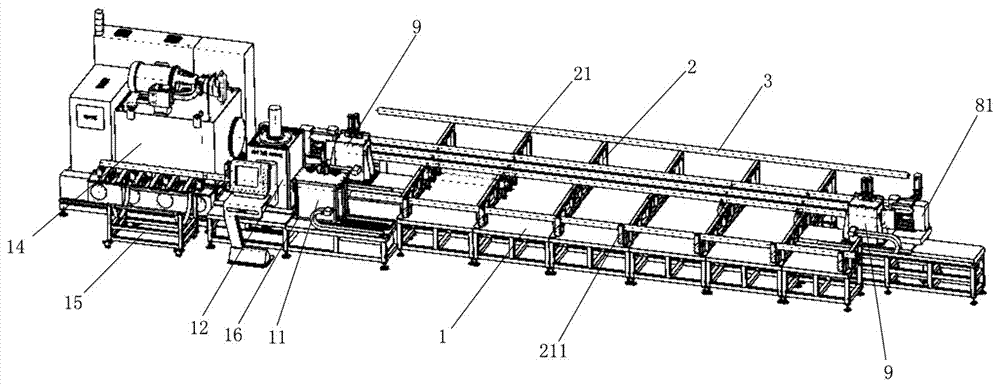
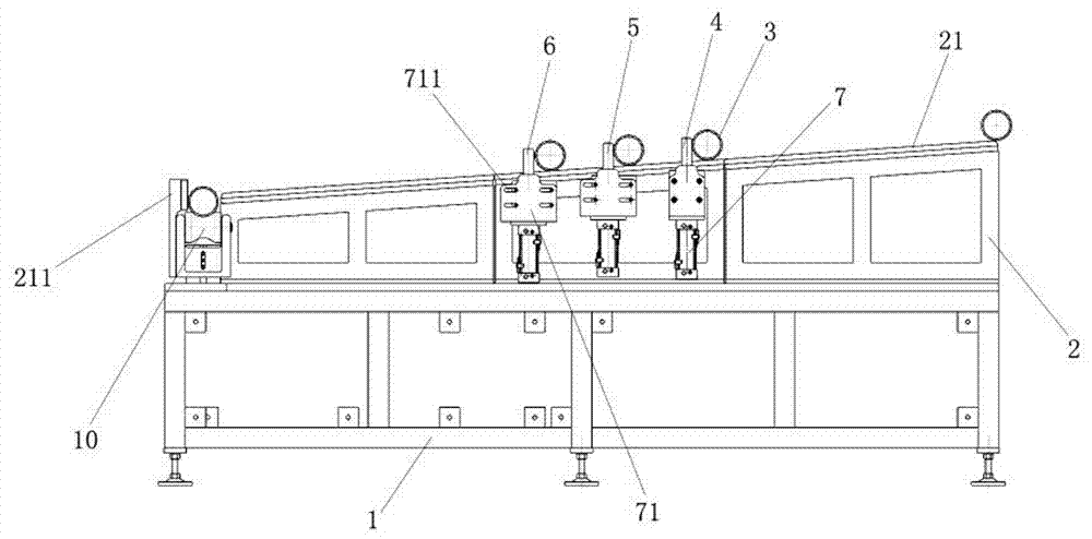
[0036]As shown in the drawings, the present embodiment is a fully automatic punching pipe production line, which includes a frame 1, on which a plurality of support stands 2 arranged parallel to each other are fixed on the top surface of the stand, between each support stand It is preferably arranged at equal intervals. The top surface of each support stand is a slope, and its height gradually decreases from the rear side of the frame to the front side. The rear side of the frame is connected to the pipe production line. The pipe production line is used to The production line in which steel plates are coiled into steel pipes and welded belongs to common knowledge in the field of pipe making technology, so this embodiment does not elaborate on its specific structure and principles, but it should be noted that the welding of pipe fittings in the...


PUM


Abstract

The invention discloses a full-automatic pipe punching production line. The full-automatic pipe punching production line can be connected with a pipe manufacturing line in a seamless joint manner. Firstly, a high-pressure pneumatic gun is used for being matched with a pulley block and directly clears away welding ribs in a welding pipe on equipment, the welding ribs are blown out of the pipe fitting and clamped out through the pulley block, and the situation that the welding ribs disturb the following pipe cutting process in resistance is prevented. Then, the high-pressure pneumatic gun can further carry out two end chamfering on the pipe fitting so as to set the length size, milling mechanisms located at the two ends of the pipe fitting carry out milling and chamfering on the margins of the pipe fitting, and therefore the precise length size can be set, and it is guaranteed that the lengths of the pipe fitting from the transportation working procedure to the pipe cutting working procedure are equal. In addition, the pipe fitting to be machined is fed in a full-automatic manner and transported to a punching station to be clamped and punched, the waste material of the previous pipe fitting can be cleared away without shutdown, time is saved, and the working efficiency is improved. In addition, in the punching working procedure, punching is adopted to replace a saw web, and the working efficiency during volume production is remarkably improved.

Description

technical field [0001] The invention relates to the technical field of pipe fitting production, in particular to a fully automatic punching pipe production line, which is generally matched with a pipe making production line, and is used to punch pipe fittings into specified lengths according to production requirements and automatically transport them to the material box middle. Background technique [0002] In the prior art, sawing is generally used for cutting pipe fittings, that is, the pipe fittings are first fixed on the workbench through clamps, and then the pipe fittings are cut from one side to the other by a high-speed rotating saw blade. The sawing process In order to ensure the flatness of the pipe fitting port after cutting, the feed speed of the saw blade toward the pipe fitting is relatively slow, which results in a relatively long time for pipe cutting; in addition, the existing pipe cutting equipment and pipe making equipment are relatively independent. After...

Claims


Application Information

Patent Timeline
Patent Type & Authority Applications(China)
IPC IPC(8): B21D28/02B21D28/04B21D28/14B21D43/16B21D43/00B21D43/08B21D43/28B08B9/032
CPCB08B9/0321B21D28/02B21D28/04B21D28/14B21D43/003B21D43/006B21D43/08B21D43/16B21D43/285
Inventor 陆志伟
Owner NINGBO TRIZ AUTOMATIC EQUIP
Why Eureka
Try Eureka