
Improved oxidation ditch cycle multiplication system

An oxidation ditch and aerobic zone technology, applied in chemical instruments and methods, aerobic and anaerobic process treatment, water pollutants, etc. Problems such as limited effects

Pending Publication Date: 2017-12-08
LINGZHI ENVIRONMENTAL PROTECTION CO LTD +1
View PDF5 Cites 6 Cited by
  • Summary
  • Abstract
  • Description
  • Claims
  • Application Information

AI Technical Summary

Problems solved by technology

Because it adopts technologies such as low dissolved oxygen and high sludge concentration, it has a good effect on BOD removal and nitrogen removal, but it has the following shortcomings: 1) Since it has no obvious anaerobic zone / anoxic zone, The effect of denitrification and phosphorus removal is very limited; 2) The sedimentation area is set as a rectangular sedimentation tank with fillers inside, which is not suitable for projects with large sewage volumes, and is not suitable for situations where there is a lot of mud production, and the replacement of fillers is inconvenient; 3) Sludge backflow is mainly controlled by a pusher installed in the influent mixing reaction area. It is inconvenient to adjust the sludge backflow and the operation is not flexible enough.

Method used


Image

  • Improved oxidation ditch cycle multiplication system
  • Improved oxidation ditch cycle multiplication system
  • Improved oxidation ditch cycle multiplication system

Examples


Embodiment 1

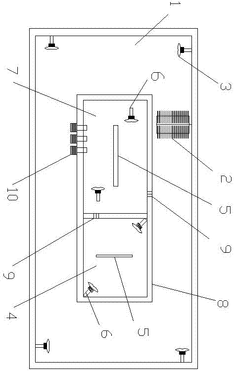
[0019] Embodiment 1: see figure 1 , this embodiment is designed for wastewater that needs nitrogen and phosphorus removal at the same time, including aerobic zone 1, aerobic zone 1 is an annular ditch, and the bottom of the ditch is evenly covered with aeration tubes 2, and aerobic zone 1 is also equipped with There is a submersible thruster 3, the anaerobic zone 4 and the anoxic zone 7 are placed in the annular ditch, and a common wall 8 is arranged between the anaerobic zone 4, the anoxic zone 7 and the aerobic zone 1; Both the oxygen zone 4 and the anoxic zone 7 are provided with a partition wall 5 and a submersible mixer 6, and the partition wall 5 and the equipped submersible mixer 6 work together to form a small hydraulic cycle; the anaerobic zone 4 and the anoxic zone 7 pass through a public The through hole 9 on the wall 8 is connected, and the anoxic zone 7 and the aerobic zone 1 are connected through the through hole 9 on the common wall 8; the nitrifying liquid in t...

Embodiment 2

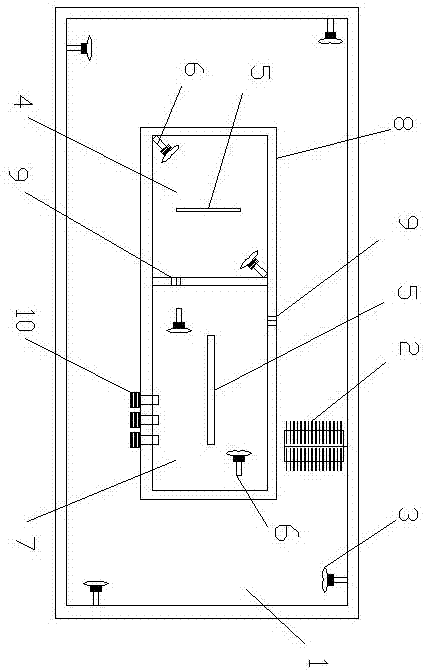
[0020] Example 2: see figure 2 , as in Example 1, the influent and return sludge first enter the anoxic zone 7, then enter the anaerobic zone 4 and the aerobic zone 1 in turn, forming an improved inverted A 2 / O oxidation ditch system.

Embodiment 3

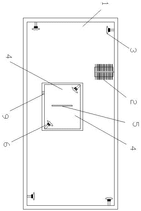
[0021] Embodiment 3: see image 3 , designed for wastewater that only needs to remove phosphorus but not nitrogen, as in Example 1, reduce the link of the anoxic zone 7 and the return pump 10 in the annular ditch to achieve the purpose of removing pollutants such as phosphorus and organic matter, and form an improved A / O (anaerobic / aerobic) oxidation ditch system.


PUM


Abstract

The invention relates to an improved oxidation ditch cycle multiplication system. The improved oxidation ditch cycle multiplication system comprises an aerobic region, an anaerobic region and an anoxic region, wherein the aerobic region is an annular ditch, and a water flow propelling device is arranged in the aerobic region; the anaerobic region and the anoxic region are arranged in the annular ditch, and a public wall body is arranged among the aerobic region, the anaerobic region and the anoxic region; and partition walls and submersible mixers are arranged in the anaerobic region and the anoxic region. The system is provided with the obvious aerobic region, anaerobic region and anoxic region, and the three or two regions can be flexibly combined into the system according to the wastewater quality characteristics, so that the treatment purposes of phosphorous removal, denitrification and organic matter removal are achieved; and furthermore, the aerobic region is set as the annular ditch, and one or two of the anaerobic region and the anoxic region are put in the annular ditch, and the joints of the three region share the same public wall body, so that the occupied area and the construction cost are saved.

Description

technical field [0001] The invention relates to the field of sewage treatment, in particular to an improved oxidation ditch circulation multiplication system. Background technique [0002] A / O and A 2 The / O process is the most representative sewage treatment process created by humans based on the basic principle of activated sludge process for sewage treatment, aiming at organic pollutants (BOD), phosphorus (P) and nitrogenous pollutants (N) in sewage. It is also the most widely used. A is the initial letter of the English word Anaerobic or Anoxic, representing anaerobic or anoxic, and O is the initial letter of the word Oxic, representing aerobic. Anaerobic, anoxic and aerobic are the necessary biochemical environments for the activated sludge process to remove P, N and BOD pollution respectively. Therefore, to remove pollutants such as P, N and BOD in sewage, it is necessary to provide and create a good anaerobic environment, anoxic environment and aerobic environment ...

Claims


Application Information

Patent Timeline
IPC IPC(8): C02F3/30C02F101/30
CPCC02F3/301C02F3/302C02F3/308C02F2101/30C02F2203/006
Inventor 凌建军梁艳杰邵飞姜宇辰王致政
Owner LINGZHI ENVIRONMENTAL PROTECTION CO LTD
Learn More