Sludge dehumidifying and drying device

A technology of sludge and jet device, applied in sludge treatment, water/sludge/sewage treatment, dewatering/drying/concentrated sludge treatment, etc., can solve the problems of high fabrication difficulty, poor equipment stability, complex equipment structure, etc. , to reduce the moisture content and improve the drying effect.

Inactive Publication Date: 2017-12-08
临泉县生产力促进中心
View PDF0 Cites 7 Cited by
  • Summary
  • Abstract
  • Description
  • Claims
  • Application Information

AI Technical Summary

Problems solved by technology

[0004] The traditional sludge drying equipment needs a lot of auxiliary equipment, the equipment structure is complicated, the manufacturing difficulty is high, the equipment stabi

Method used


Image

  • Sludge dehumidifying and drying device
  • Sludge dehumidifying and drying device
  • Sludge dehumidifying and drying device

Examples


Example Embodiment

[0018] The technical solution of this patent will be described in further detail below in conjunction with specific embodiments.
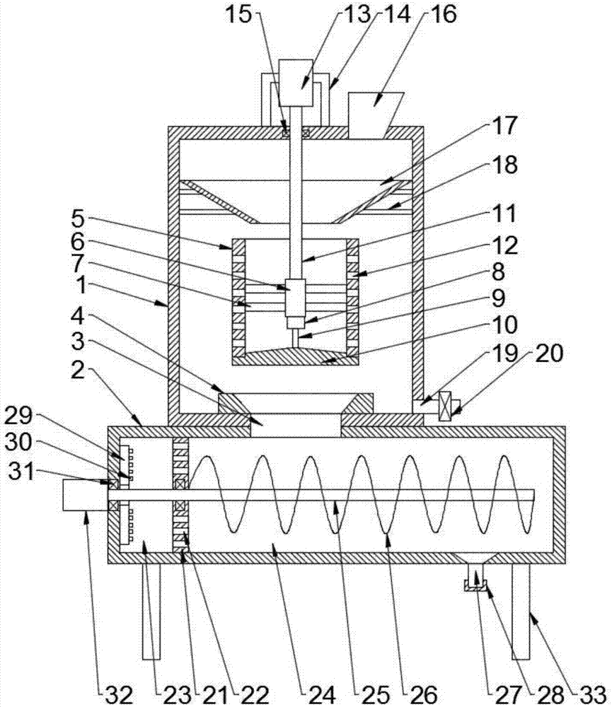
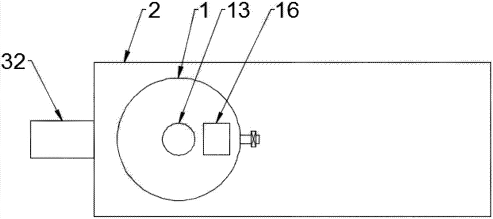
[0019] See Figure 1~3 , A sludge dehumidification and drying device, comprising a dehydration box 1 and a drying box 2, the dehydration box 1 is a cylindrical structure design, the dehydration box 1 is fixedly connected to the left side of the top surface of the drying box 1, the dehydration box 1 Through the connecting hole 3 and the drying box 2 through connection, the top end of the connecting hole 3 is connected through the first guide hopper 4, the inner cavity of the dehydration box 1 is provided with a water slinger 5, the water slinger 5 is the upper and lower ends All are designed with open cylindrical structure. The axis of the water slinger 5 coincides with the axis of the dehydration tank 1. The side wall of the slinger 5 is evenly provided with a number of dehydration holes 12, and the water slinger 5 is provided with fixed Column 6, th...


PUM


Abstract

The invention discloses a sludge dehumidification and drying device, which comprises a dehydration box and a drying box. The middle part of the inner cavity of the dehydration box is provided with a water throwing cylinder, and the water throwing cylinder is provided with a fixed column, and the bottom end of the fixed column is fixedly connected with a hydraulic cylinder. The top of the fixed column is fixedly connected to the rotating shaft. The top of the rotating shaft passes through the top wall of the dehydration box and is fixedly connected to the motor shaft of the first motor. The inner cavity of the box is divided into an air blowing chamber and a drying chamber. The drying chamber is provided with a propulsion shaft, and the propulsion shaft is provided with a stirring blade matched with the drying chamber. A number of air nozzles are evenly arranged on the top; the present invention first dries the sludge with high water content by setting a water-spinning cylinder, so that the moisture content in the sludge is greatly reduced, and after the dried sludge enters the drying box, it is Under the action of high-temperature gas, it is further heated to further discharge the water in the sludge, so that the water content in the sludge is reduced to a minimum.

Description

technical field [0001] The invention relates to the technical field of sludge treatment, in particular to a sludge dehumidification and drying device. Background technique [0002] In recent years, with the rapid development of urbanization in my country and the continuous expansion of industrial production scale, the output of municipal sludge is increasing. How to dispose and utilize municipal sludge has become a concern of people. [0003] At present, the sludge dehumidification and drying technology uses low-temperature drying equipment to directly enter the sludge into the dehumidification and drying machine for drying. Sludge dehumidification and drying machine applies the principle of freezing and dehumidification. Through the dehumidification heat pump, the sludge is subjected to hot air circulation, condensation dehumidification, drying and other processes, and the humid air is cooled to below the dew point temperature, and moisture is precipitated, and then heated ...

Claims


Application Information

Patent Timeline
IPC IPC(8): C02F11/12
CPCC02F11/127C02F11/12
Inventor 李中利
Owner 临泉县生产力促进中心
Why Eureka
Try Eureka