
In-hole point anchor slide-resistant pile barricade

A technology of anti-sliding piles and retaining walls, applied in water conservancy projects, artificial islands, underwater structures, etc., can solve problems such as difficulty in preventing emergencies, long time of anti-sliding effect, cumbersome construction, etc., and achieve short construction period , low cost, and structural safety

Inactive Publication Date: 2017-12-08
芜湖凡达机械科技有限公司
View PDF4 Cites 4 Cited by
  • Summary
  • Abstract
  • Description
  • Claims
  • Application Information

AI Technical Summary

Problems solved by technology

With the occurrence of earthquakes in our country more and more frequently, various slope geological disasters caused by earthquakes have also become more and more frequent, and landslide control has become an increasingly important project. Compared with other anti-slide projects, such as anti-slide Compared with sliding retaining walls, anchor rods, etc., anti-slide piles have the characteristics of strong sliding resistance and wide application range, and are especially suitable for treating large-scale landslides with deep sliding surfaces. The anti-sliding pile layer in the form of anti-sliding piles cannot be exposed, but basically the foundation pit is excavated first, then the steel cage is tied, and finally the concrete is poured. It is difficult to prevent some emergencies. Therefore, we provide a new type of anchored anti-sliding pile retaining wall in the hole

Method used


Image

  • In-hole point anchor slide-resistant pile barricade
  • In-hole point anchor slide-resistant pile barricade
  • In-hole point anchor slide-resistant pile barricade

Examples


Embodiment

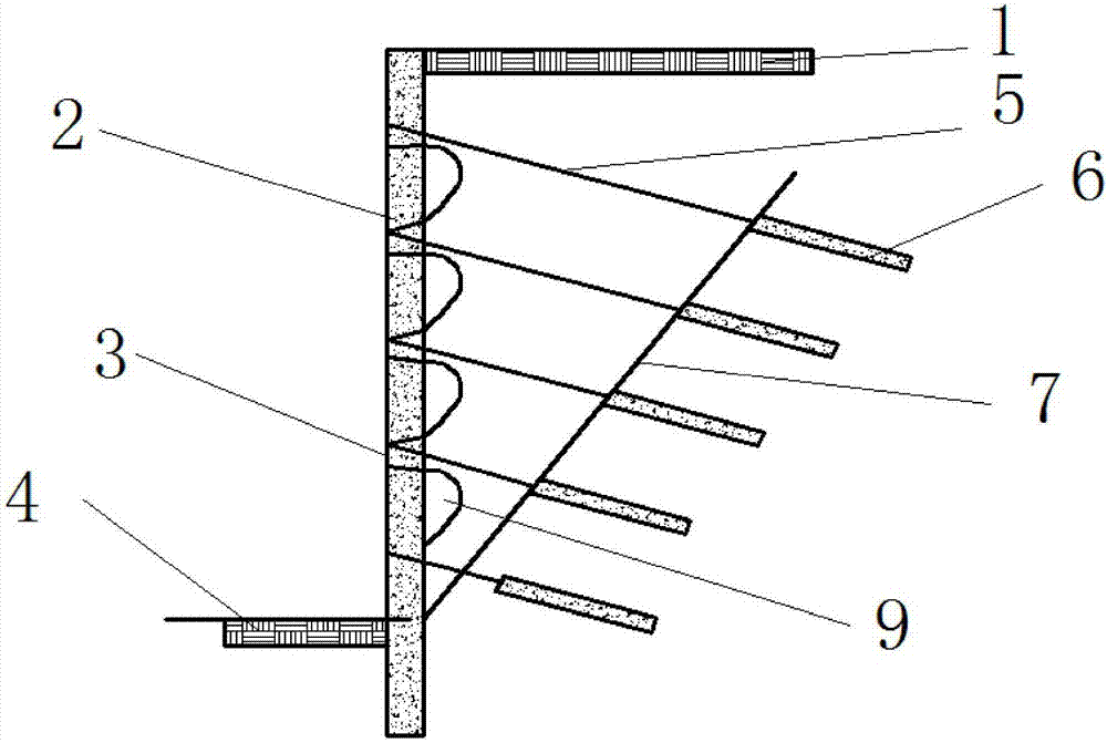
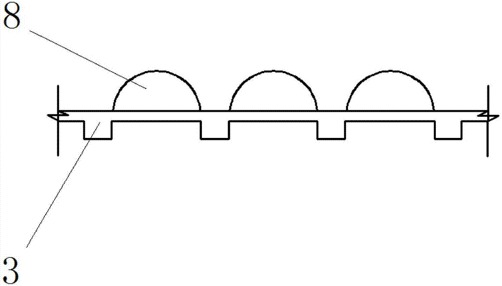
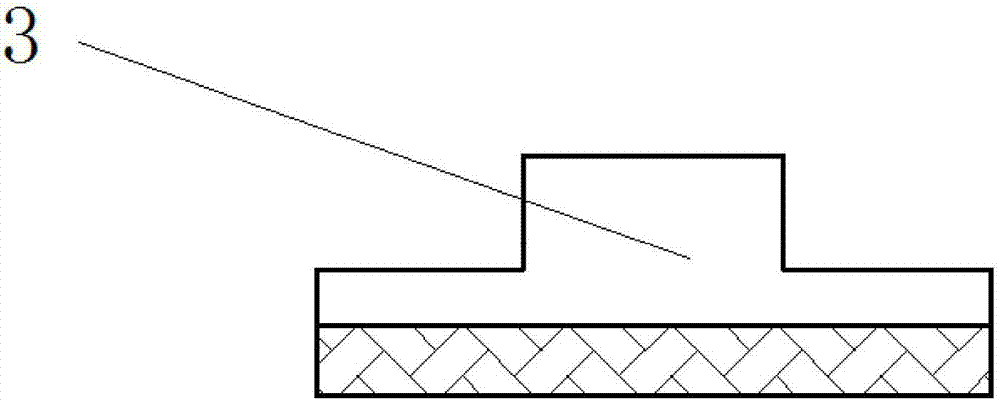
[0015] Example: see Figure 1-3 , the present invention is a new type of in-hole point anchor anti-slide pile retaining wall. An anti-slide pile 2 is arranged in between, and the surface of the anti-slide pile 2 is provided with an anchor cable 5 at intervals, and one end of the anchor cable 5 is provided with an anchor section 6, and a point anchor is provided between the anchor cable 5 and the anti-slide pile 2 3. There is a horizontal collapse arch 8 and a vertical collapse arch 9 between the point anchors 3, a slip fracture surface 7 is provided between the anchor section 6 and the anchor cable 5, and the anchor section 6 is set on the slip fracture surface. Inside face 7.

[0016] The bottom of the anti-slide pile 2 is arranged in the soil layer at the bottom of the slope 4 .

[0017] It should be noted that the present invention is a new type of point-anchor anti-slide pile retaining wall in the hole. The beam structure of the traditional anti-slide pile is changed to ...


PUM


Abstract

The invention belongs to the field of slope treatment and discloses a novel in-hole point anchor slide-resistant pile barricade. The in-hole point anchor slide-resistant pile barricade comprises a slope top, slide-resistant piles, point anchors, anchorage sections and horizontal slumping arches, wherein the slide-resistant piles are arranged between the slope top and a slope bottom; anchor cables are disposed on the surfaces of the slide-resistant piles at intervals; one end of each anchor cable is provided with one anchorage section; the point anchors are disposed between the anchor cables and the slide-resistant piles; the horizontal slumping arches and vertical slumping arches are disposed between the point anchors; and a sliding fracture surface is disposed between the anchorage sections and the anchor cables, and the anchorage sections are arranged inside the sliding fracture surface. An in-pile point anchor technology combines the advantages of both a piled anchor method and a point anchor method, the structure safety can be ensured in the construction period, and the construction cost of the projects can be reduced; the novel in-hole point anchor slide-resistant pile barricade has the same construction method as that of a traditional piled anchor system; the structure of each pile body is small in size, the number of steel bars is small, the construction cost is low, and the construction period is short; and the defect that traditional point anchor support methods do not have vertical supports is avoided.

Description

technical field [0001] The invention relates to a retaining wall, in particular to a novel point-anchored anti-sliding pile retaining wall in a hole. Background technique [0002] As we all know, today, the difficulties faced by slope engineering design are: 1) In urban construction, the limitation and complexity of environmental conditions have increased significantly; 2) Due to the limitation of environmental conditions, geological conditions are not selective; Increased restrictions on catastrophic environments such as shocks. Under these conditions, the design of slope engineering has become very difficult. Anti-slide piles are piles that penetrate the slope and go deep into the sliding bed to support the sliding force of the sliding body and stabilize the slope. It is mainly to use the anchor pipe effect and passive resistance of the stable rock formation below the sliding surface of the landslide to balance the sliding thrust of the landslide. With the occurrence of ...

Claims


Application Information

Patent Timeline
IPC IPC(8): E02D29/02
CPCE02D29/0233
Inventor 不公告发明人
Owner 芜湖凡达机械科技有限公司
Features
  • Generate Ideas
  • Intellectual Property
  • Life Sciences
  • Materials
  • Tech Scout
  • Unparalleled Data Quality
  • Higher Quality Content
  • 60% Fewer Hallucinations
Learn More