All-closed nuclear drum vacuum valve main shaft sealing structure

A fully-enclosed, spindle-sealing technology, which is applied to engine seals, engine components, mechanical equipment, etc., can solve problems that cannot meet the needs of large-diameter drum seals, and achieve the effect of safe and reliable sealing structure and optimized design

Inactive Publication Date: 2017-12-08
中核第七研究设计院有限公司
5 Cites 0 Cited by

AI-Extracted Technical Summary

Problems solved by technology

With the expansion of the separation work of the cascade system, the caliber of the nuclear vacuum valve is also increasing. The traditional sealing structure can no longer meet the ...

Method used

[0019] The fourth seal: including the upper sealing ring 10 at the support 14 and the lip seal ring 15 two-part sealing, mainly used for the sealing of the main shaft 3 and the sleeve 11. The upper sealing ring 10 is installed between the support 14 and the main shaft 3 , and the lip seal ring 15 is installed between the sleeve 11 and the main shaft 3 . This part of the...

Abstract

The invention belongs to the technical field of nuclear vacuum valves, and in particular relates to a fully-enclosed main shaft sealing structure of nuclear rotary drum vacuum valves. The lower sealing ring is fixed between the pressure plate and the assembly cover; the sealing ring is fixed between the shell and the assembly cover; the main shaft is pressed on the lower sealing ring; the diaphragm is welded between the connecting shell and the support; the upper sealing ring is installed on the support Between the seat and the main shaft; the lip seal ring is installed between the sleeve and the main shaft; the matching disc spring group is pressed above the sleeve; the nut is installed above the matching disc spring group; one end of the rubber bowl is fixed on the main shaft through a clamp The other end is fixed on the housing by a large nut. The invention adopts five sealing structures, which fully guarantee the sealing of the main shaft part of the valve. At the same time, the rubber bowl is used to transform the dynamic sealing into static sealing, the design is optimized, and the sealing structure is safe and reliable.

Application Domain

Engine seals

Technology Topic

EngineeringMechanical engineering

Image

  • All-closed nuclear drum vacuum valve main shaft sealing structure

Examples

  • Experimental program(1)

Example Embodiment

[0012] The present invention will be described in detail below with reference to the accompanying drawings and specific embodiments.
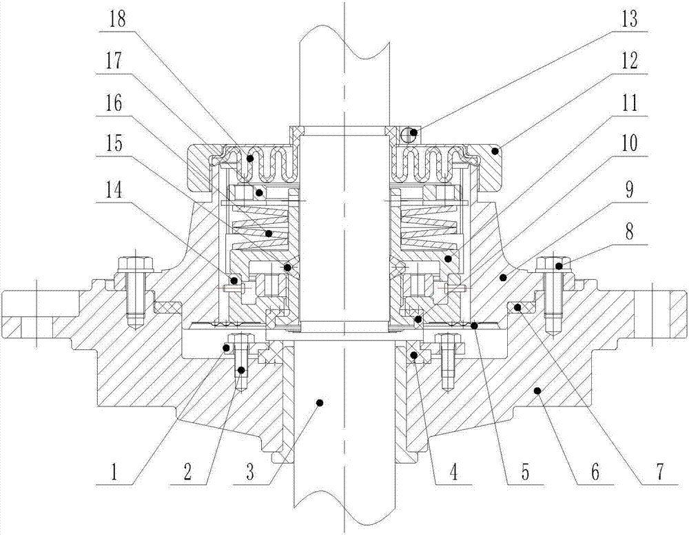
[0013] like figure 1 As shown in the figure, the fully enclosed main shaft sealing structure of the rotary drum vacuum valve for nuclear use according to the present invention includes a bolt A2, a lower sealing ring 4, a diaphragm 5, a sealing ring 7, a bolt B8, an upper sealing ring 10, and a large nut. 12. Clamp 13, lip seal ring 15, butt-type disc spring group 16, nut 17, rubber bowl 18;
[0014] The lower sealing ring 4 is fixed between the pressure plate 1 and the assembly cover 6 by the bolts A2; the sealing ring 7 is fixed between the shell 9 and the assembly cover 6 by the bolts B8; the main shaft 3 is pressed on the lower sealing ring 4; Press welding to connect the housing 9 and the support 14; the upper sealing ring 10 is installed between the support 14 and the main shaft 3; the lip seal ring 15 is installed between the sleeve 11 and the main shaft 3; Above the sleeve 11; the nut 17 is installed above the abutment type disc spring group 16; the rubber bowl 18 is installed between the housing 9 and the main shaft 3 through the large nut 12 and the clamp 13.
[0015] During the valve opening and closing process, the main shaft 3 and the clamp 13 are rotated, the rubber bowl 18 is twisted, and the rest of the parts are stationary. There are five seals to completely seal the main shaft part.
[0016] The first seal: the sealing ring 7 between the assembly cover 6 and the housing 9 realizes the outer sealing of the main shaft part, and the sealing pressing force is provided by the bolt B8, which is installed on the assembly cover 6.
[0017] The second seal: due to the rotation of the main shaft 3, the gaseous medium will leak from the valve body to the space between the assembly cover 6 and the casing 9. The lower sealing ring 4 between the pressure plate 1 and the assembly cover 6 realizes the main shaft 3 and the assembly cover. 6. Preliminary sealing between the housings 9, the sealing pressing force is provided by the bolt A2, which is installed on the assembly cover 6.
[0018] The third seal: the diaphragm 5 is roll welded between the casing 9 and the support 14 to further seal the assembly cover 6 and the casing 9. At the same time, the diaphragm 5 needs to have a certain strength and rigidity to withstand the medium pressure.
[0019] Fourth seal: including two parts of the upper seal ring 10 at the support 14 and the lip seal ring 15, which are mainly used for the seal of the main shaft 3 and the sleeve 11. The upper sealing ring 10 is installed between the support 14 and the main shaft 3 , and the lip seal ring 15 is installed between the sleeve 11 and the main shaft 3 . This part of the sealing pressing force is provided by the nut 17 pressing the butt-type disc spring group 16, and the deformation of the abutting-type disk spring group under the same pressing force is smaller, which reduces the size of the valve. The nut 17 is installed above the abutment type disc spring group 16 , and the abutment type disc spring group 16 is pressed above the sleeve 11 .
[0020] Fifth seal: After the above four seals, there may still be a very small part of the material that will leak into the space of the butt-type disc spring group 16. This part is sealed by the rubber bowl 18 on the main shaft 3. The rubber bowl 18 is supported by the clamp 13 and The large nut 12 connects the main shaft 3 and the housing 9 . One end of the rubber bowl 18 is fixed on the main shaft 3 through the clamp 13 , and the other end is fixed on the casing 9 through the large nut 12 . When the valve is opened and closed, the main shaft 3 rotates, the large nut 12 is stationary, and the rubber bowl 18 converts the dynamic seal into a static seal, so the rubber bowl 18 is required to have good elasticity.

PUM

no PUM

Description & Claims & Application Information

We can also present the details of the Description, Claims and Application information to help users get a comprehensive understanding of the technical details of the patent, such as background art, summary of invention, brief description of drawings, description of embodiments, and other original content. On the other hand, users can also determine the specific scope of protection of the technology through the list of claims; as well as understand the changes in the life cycle of the technology with the presentation of the patent timeline. Login to view more.

Similar technology patents

Multi-grade accordion type honeycomb structure

InactiveCN109990193AGood bearing capacityoptimized design
Owner:XI AN JIAOTONG UNIV

Traffic light based on image recognition control

Owner:SUZHOU INDAL PARK INSTITUE OF VOCATIONAL TECH

Classification and recommendation of technical efficacy words

Why Eureka
Try Eureka