
Numerical simulation method for continuous layup of composite material at right angle

A composite material and numerical simulation technology, applied in CAD numerical modeling, electrical digital data processing, special data processing applications, etc., can solve problems such as inability to respond to force conditions, failure to consider corners, and layer continuity issues

Active Publication Date: 2021-03-09
XIAN AIRCRAFT DESIGN INST OF AVIATION IND OF CHINA
View PDF2 Cites 0 Cited by
  • Summary
  • Abstract
  • Description
  • Claims
  • Application Information

AI Technical Summary

Problems solved by technology

There is a turning lay of the prepreg in the R area, and the coordinate system will change. In the general overall finite element analysis, each independent surface refers to its own rectangular coordinate system, and the problem of rotation angle and layup continuity is not considered, and the output results cannot reflect the reality. The stress of the structure, such as the composite wing rib of a certain type of aircraft, due to the early delamination of the flange and the web corner area, the composite wing rib scheme was abandoned

Method used


Image

  • Numerical simulation method for continuous layup of composite material at right angle
  • Numerical simulation method for continuous layup of composite material at right angle
  • Numerical simulation method for continuous layup of composite material at right angle

Examples


Embodiment Construction

[0017] In order to make the objectives, technical solutions and advantages of the present invention clearer, the technical solutions in the embodiments of the present invention will be described in more detail below in conjunction with the drawings in the embodiments of the present invention.

[0018] It should be noted that the embodiments described below with reference to the accompanying drawings are exemplary and intended to explain the present invention, but should not be construed as limiting the present invention. In the drawings, the same or similar reference numerals denote the same or similar elements or elements having the same or similar functions throughout. The described embodiments are part of the embodiments of the present invention, but not all of the embodiments. In the case of no conflict, the embodiments in the present application and the features in the embodiments can be combined with each other. Based on the embodiments of the present invention, all othe...


PUM


Abstract

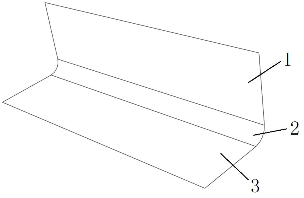
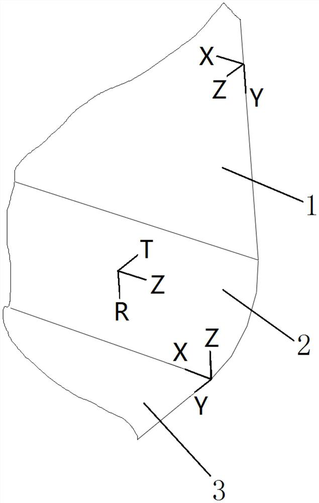
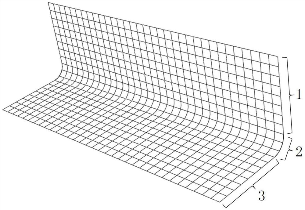
The present invention relates to the technical field of aircraft structure design, and specifically provides a numerical simulation method for continuous layering of right-angle turns of composite materials. Firstly, a 3D shell geometric model of composite materials is established, including horizontal bead areas, corner areas and vertical bead areas, and then Establish the Cartesian coordinate system of the horizontal bead area and the Cartesian coordinate system of the vertical bead area, and establish the cylindrical coordinate system of the corner area, and then define the composite layer properties of the horizontal bead area, corner area and vertical bead area respectively, and according to the law To adjust the reference direction of the layup datum in the above three areas respectively, select the coordinate system corresponding to the layup in the above three areas, and ensure that the layup in the above three areas is continuous and the angle of the same layup is consistent, and then the composite material 3D shell geometry The model is meshed, constraints and loads are imposed on the geometric model to obtain a finite element model, and finally the static strength field variables of the finite element model are obtained.

Description

technical field [0001] The invention relates to the technical field of aircraft structure design, in particular to a numerical simulation method for quarter-turn continuous layering of composite materials. Background technique [0002] The structural characteristics of the R zone at the junction of the vertical edge plates of the composite laminate structure widely exist in various aircraft composite parts, such as stringers, ribs and beams. There is a turning lay of the prepreg in the R area, and the coordinate system will change. In the general overall finite element analysis, each independent surface refers to its own rectangular coordinate system, and the problem of rotation angle and layup continuity is not considered, and the output results cannot reflect the reality. The stress situation of the structure, such as the composite wing rib of a certain type of aircraft, due to the early delamination of the edge strip and the corner area of ​​the web, led to the abandonmen...

Claims


Application Information

Patent Timeline
Patent Type & Authority Patents(China)
IPC IPC(8): G06F30/23G06F30/15G06F113/26G06F111/10
CPCG06F30/15G06F30/23
Inventor 曹鹏飞
Owner XIAN AIRCRAFT DESIGN INST OF AVIATION IND OF CHINA
Learn More