Rolling walking rack achieving high drive torque

A walking frame and driving torque technology, applied in the field of rolling walking frame and rolling walking frame structure, can solve the problems of inability to realize agricultural machinery field ploughing, insufficient driving force of the drive axle, and the inability of agricultural machinery to climb out, etc., and achieve convenient assembly. and replacement, improve traction driving force, the effect of simple structure

Pending Publication Date: 2017-12-12
彭广平
View PDF8 Cites 1 Cited by
  • Summary
  • Abstract
  • Description
  • Claims
  • Application Information

AI Technical Summary

Problems solved by technology

The invention patent distributes the power of the engine through two transmission shafts to the driving axle for driving the agricultural machinery and the auxiliary equipment for the farming machinery, although it realizes the multi-purpose of the agricultural machinery, but due to the Occupying a certain power consumption of the engine will inevitably cause insufficient driving force of the drive axle, causing the agricultural machine to fall into the pit and cannot climb out, and cannot work after loading heavy farming auxiliary equipment, that is, the original power is not enough to drive the agricultural machine. Walking, so that it is impossible to realize the field work of agricultural machinery

Method used


Image

  • Rolling walking rack achieving high drive torque
  • Rolling walking rack achieving high drive torque
  • Rolling walking rack achieving high drive torque

Examples


Embodiment Construction

[0029] In order to make the object, technical solution and advantages of the present invention clearer, the present invention will be further described in detail below in conjunction with the accompanying drawings and embodiments. It should be understood that the specific embodiments described here are only used to explain the present invention, not to limit the present invention.

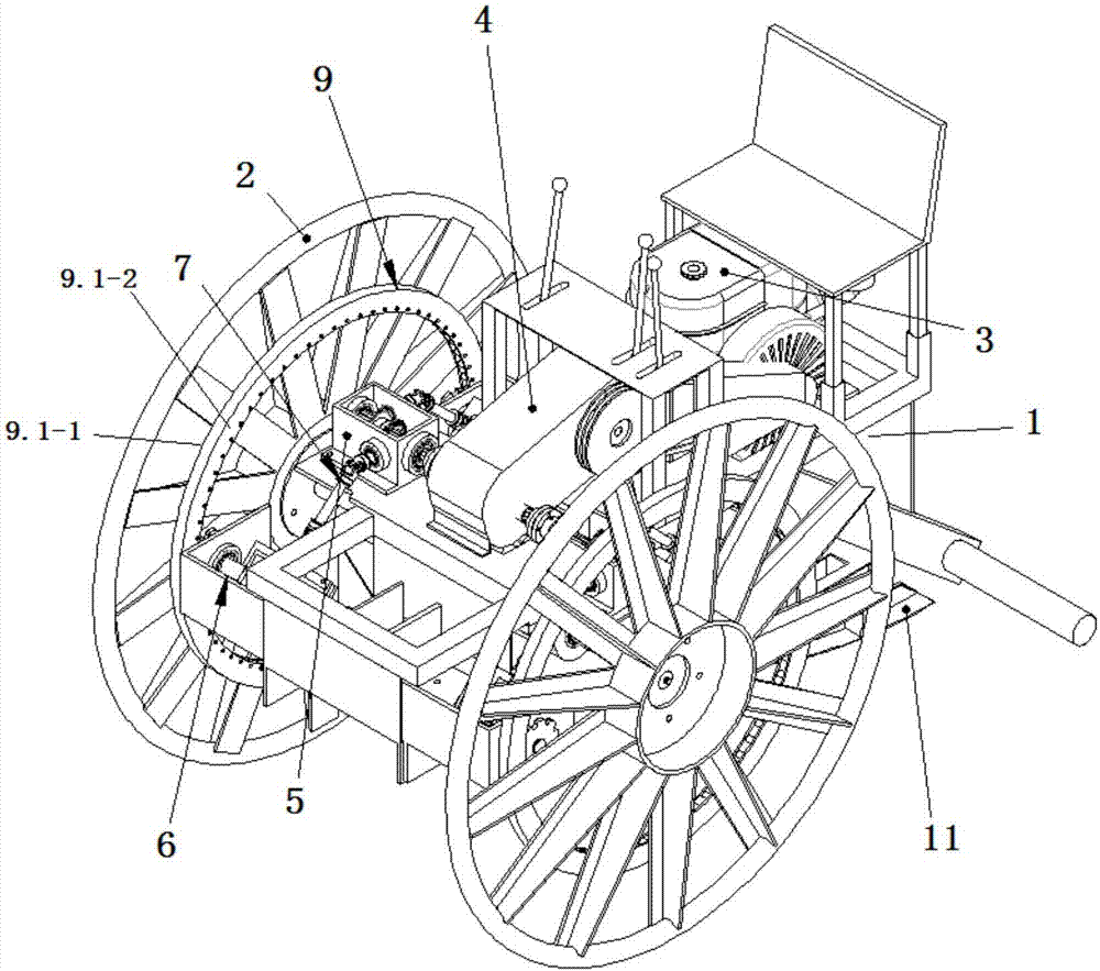
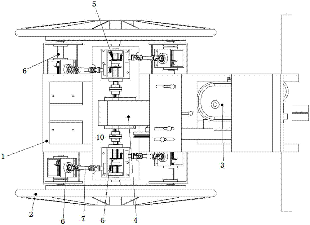
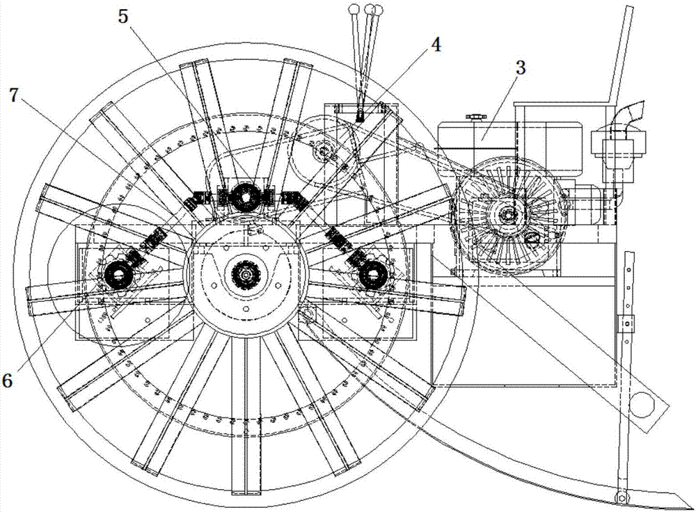
[0030]As can be seen from the structural schematic diagram of a rolling walking frame with a large driving torque shown in the specification, a rolling walking frame with a large driving torque of the present invention includes a frame 1, and main wheels 2 are connected to both sides of the frame 1 (this embodiment 2 in the example, also can be 2n (n is greater than 1)), be provided with on the frame 1 and be used to drive the power unit 3 of main wheel 2 revolutions and gearbox 4, the output end of power unit 3 and gearbox 4 input The left and right sides of the gearbox 4 are symmetrically arrange...


PUM


Abstract

The invention discloses a rolling walking rack achieving high drive torque. The rack comprises a rack body, main wheels are connected to the two sides of the rack body, a power device used for driving the main wheels to turn around and a gearbox are arranged on the rack, and the output end of the power device is connected with the input end of the gearbox; transmission shaft distribution boxes used for distributing power are symmetrically arranged on the left side and the right side of the gearbox, and small thumbwheel boxes used for driving the main wheels are symmetrically arranged at the front end and the rear end of each transmission shaft distribution box; the input end of each transmission shaft distribution box is connected with the output end of the gearbox, and the output end of each transmission shaft distribution box is connected with the input end of the corresponding small thumbwheel box through a universal coupling; a driving thumbwheel is connected to the output end of each small thumbwheel box; a transmission gear ring capable of being matched with each driving thumbwheel is fixedly connected to the inner side of the corresponding main wheel in a coaxial mode. Accordingly, the structure is simple, manufacturing and using are convenient, and the drive torque of the rolling walking rack is effectively increased.

Description

technical field [0001] The invention relates to a rolling traveling frame structure, which belongs to the technical field of agricultural machinery equipment, in particular to a rolling traveling frame with a large driving torque. Background technique [0002] Most of the existing rolling walking equipment adopts a power unit and a gearbox to distribute power to each traveling wheel. At the same time, the power output shaft distributed by the gearbox is generally arranged coaxially with the traveling wheels, directly driving the traveling wheels to rotate to drive the entire frame. walk. In special cases (such as walking equipment falling into a deep pit or the load on the frame is too heavy), the above-mentioned rolling walking equipment must manually move the agricultural machinery or vehicle out of the deep pit or manually unload the heavy objects before the equipment can continue to walk; especially For agricultural machinery, since various auxiliary farming components ...

Claims


Application Information

Patent Timeline
Patent Type & Authority Applications(China)
IPC IPC(8): A01B51/02
CPCA01B51/026
Inventor 彭广平
Owner 彭广平
Why Eureka
Try Eureka