
Heavy manipulator device for production line machining

An assembly line and manipulator technology, applied in the direction of manipulators, program-controlled manipulators, metal processing, etc., can solve problems such as threats to the safety of workers around them, difficulties in processing high-quality parts, etc., and achieve practical functions, improve work efficiency, and reasonable structure. Effect

Active Publication Date: 2017-12-12
LINYI UNIVERSITY
View PDF7 Cites 4 Cited by
  • Summary
  • Abstract
  • Description
  • Claims
  • Application Information

AI Technical Summary

Problems solved by technology

[0005] The technical problem solved by the present invention is that some large-volume, high-quality parts in the modern production line are difficult to process and pose a threat to the life safety of the surrounding workers, and adopt modern technology to realize the automatic production of the line and reduce the workload of the workers. Improved production efficiency

Method used

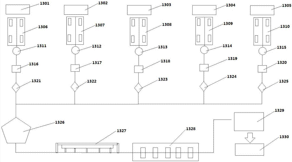
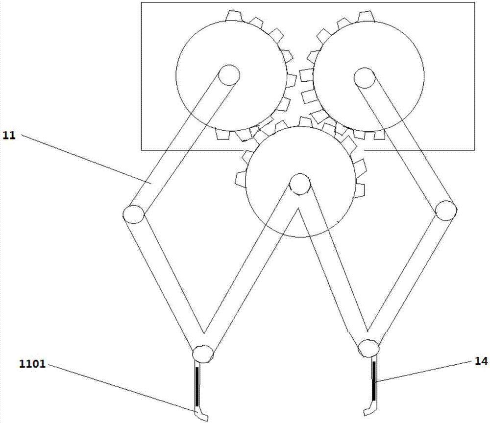

Image

  • Heavy manipulator device for production line machining
  • Heavy manipulator device for production line machining
  • Heavy manipulator device for production line machining

Examples


Embodiment

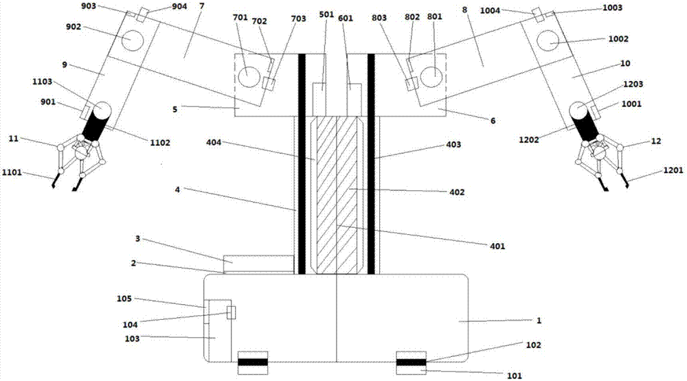
[0027] Example: such as figure 1 As shown, a heavy-duty manipulator device for assembly line processing mainly includes: base 1, drive motor mounting plate 2, drive motor 3, column 4, left arm seat 5, right arm seat 6, left arm 7, right arm Arm 8, left forearm 9, right forearm 10, left parallel claw 11, right parallel claw 12.

[0028] Such as figure 1 As shown, the driving motor mounting plate 2 is located on the upper surface of the base 1, and the driving motor 3 is installed on the driving motor mounting plate 2. The base 1 also includes: supporting wheels 101, supporting wheel bearings 102, host 103, magnetic tape 104, and screen 105 , the supporting wheel bearing 102 is located at the bottom of the base 1 and passes through the supporting wheel 101, the host 103 is installed inside the base 1, the magnetic tape 104 is installed on the host 103, the screen 105 is connected to the host 103 and is located on the outer surface of the base side superior.

[0029] Such as fi...


PUM


Abstract

The invention discloses a heavy manipulator device for production line machining. The device mainly comprises a base, a driving motor mounting plate, a driving motor, a stand column, a left rotating arm base, a right rotating arm base, a left large arm, a right large arm, a left small arm, a right small arm, a left parallel jaw and a right parallel jaw; the driving motor mounting plate is positioned on the upper surface of the base; the driving motor is mounted on the driving motor mounting plate; the stand column is mounted on the base; one end of the left rotating arm base is mounted on the stand column, and the other end is connected with the left large arm; the other end of the left large arm is connected with the left small arm; the other end of the left small arm is connected with the left parallel jaw; one end of the right rotating arm base is mounted on the stand column, and the other end is connected with the right large arm; the other end of the right large arm is connected with the right small arm; and the other end of the right small arm is connected with the right parallel jaw. The device uses a modernization technology for realizing automatic work, guarantees the life safety of workers, and improves the working efficiency.

Description

technical field [0001] The invention relates to a production line device, in particular to a heavy manipulator device for production line processing. Background technique [0002] At present, the production line of the existing technology is delivered by the transmission chain of the production line, which is very close to the operator. In this way, sometimes the processed workpiece is large in size and high in quality, which interferes with the operator and threatens the life safety of the worker, reducing the Productivity. [0003] Existing mechanical claws have cylinders, pistons, push rods, claws, etc., by pressing the cylinder to push the piston machine push rod to drive the claws to grasp and open, or to drive the claws to grasp and open by controlling the rotation of the gears by the motor. Open, so as to realize the action of grasping and releasing the workpiece. But sometimes, when the mechanical claw does not pick up the workpiece that needs to be moved, or does ...

Claims


Application Information

Patent Timeline
IPC IPC(8): B25J9/00B25J9/04B25J18/04B25J15/08B25J19/00B23P15/00B23Q41/02B23Q7/04
CPCB23P15/00B23Q7/043B23Q7/048B23Q41/02B25J9/0009B25J9/0084B25J9/046B25J15/08B25J18/04B25J19/007
Inventor 康与云
Owner LINYI UNIVERSITY
Learn More