
Dried tofu packaging inkjet printer

A technology of outer packaging and inkjet printers, applied in typewriters, printing devices, printing, etc., can solve problems such as inconsistent positions and directions, easy jamming of iron rods, irregular printing, etc., to achieve clear and accurate inkjet, eliminate The effect of static electricity and inkjet code is accurate and standard

Active Publication Date: 2019-01-08
CHONGQING HAOJIE FOOD
View PDF13 Cites 1 Cited by
  • Summary
  • Abstract
  • Description
  • Claims
  • Application Information

AI Technical Summary

Problems solved by technology

[0004] However, there are still defects in the above-mentioned device: the suspenders are prone to tilt, causing the iron rod to easily get stuck on the food packaging bags on the conveyor belt, and when the food packaging bags are placed on the conveyor belt, the position and direction are not uniform, resulting in irregular printing

Method used


Image

  • Dried tofu packaging inkjet printer
  • Dried tofu packaging inkjet printer
  • Dried tofu packaging inkjet printer

Examples


Embodiment 1

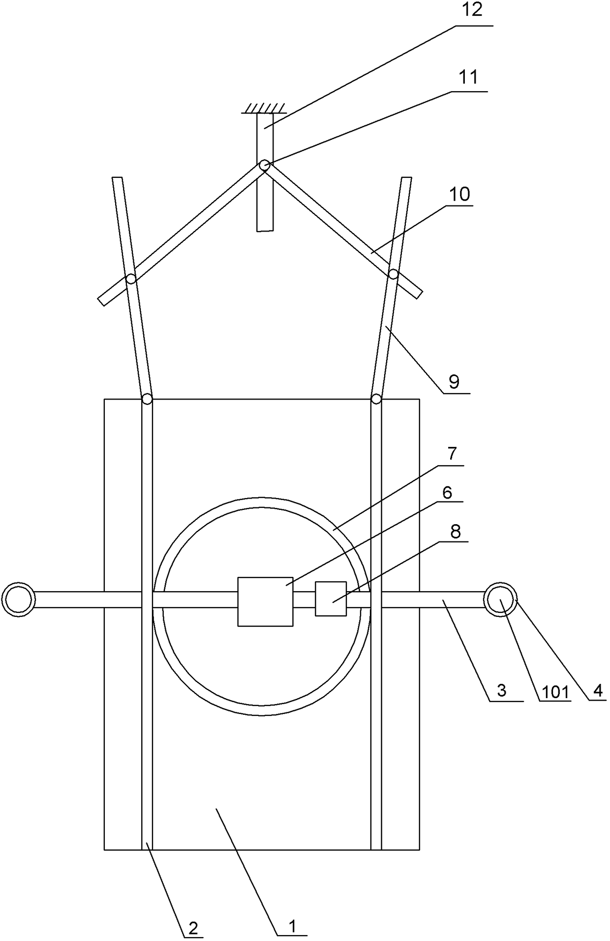
[0025] Such as figure 1 with figure 2 Shown as shown:

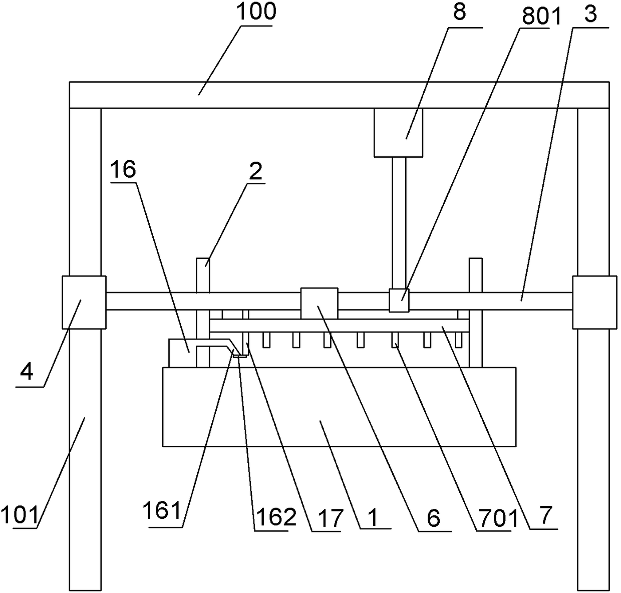
[0026] The bean curd outer packaging inkjet printer of the present invention includes a frame 100, a horizontal rod 3, a conveyor belt 1, and a coding device. The horizontal rod 3 is located above the conveyor belt 1, and both ends of the horizontal rod 3 are welded with sliding sleeves 4, and the sliding sleeve 4 is covered with On the support rod 101 on the frame 100 and can slide freely on the support rod 101, the horizontal ring 7 is horizontally welded to the bottom end of the horizontal rod 3, and the coding device 6 is welded to the horizontal rod 3, and the coding device 6 is provided with Infrared sensor, laser nozzle and controller (not shown in the figure), the coding device 6 is located in the middle of the horizontal circle 7, and the horizontal circle 7 is provided with a metal unit. The metal unit can be metal rods evenly arranged on the horizontal circle 7 701 or a metal universal wheel, or a metal surface l...

Embodiment 2

[0030] This embodiment is modified on the basis of the first embodiment. The difference from the embodiment is that the side plate 9 is not opened and closed by manual pushing, but is opened and closed by the drive of the side plate driving device. The specific structure of the drive device is as follows:

[0031] Such as Figure 4 As shown, the side plate driving device includes a cam 19, a turbine 20 and an additional pipe 18. The additional pipe 18 communicates with the blowing device 16, the turbine 20 is rotatably connected in the additional pipe 18, the turbine 20 and the cam 19 are coaxially welded, and the cam 19 is connected to the The side plate 9 abuts, and a torsion spring is provided at the hinge joint of the side plate 9 and the frame 100. The gas in the blowing device 16 enters the additional pipe 18, which drives the rotation of the turbine 20, the rotation of the turbine 20 drives the rotation of the cam 19, and the rotation of the cam 19 drives the side plate 9...

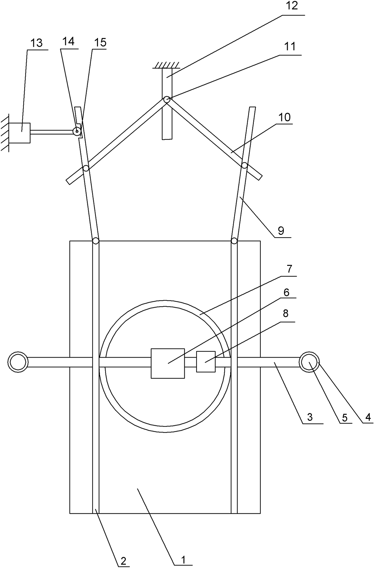
Embodiment 3

[0033] The difference between this embodiment and the second embodiment is: the structure of the side plate 9 driving device is different, and the specific structure of the side plate driving device is as follows:

[0034] Such as image 3 As shown, the side plate driving device includes a hydraulic cylinder 13, a roller 14 and a rolling groove 15. The hydraulic cylinder 13 is fixedly installed on the frame 100 by bolts. The roller 14 is rotatably connected to one end of the output rod of the hydraulic cylinder 13, and the rolling groove 15 It is opened on the side plate 9, the roller 14 is slidably installed in the rolling groove 15, and a torsion spring is installed at the hinge joint between the side plate 9 and the baffle 2. The output rod of the hydraulic cylinder 13 extends, the roller 14 rolls in the rolling groove 15, the side plate 9 rotates clockwise around the hinged joint of the side plate 9 and the baffle 2, the other side plate 9 rotates counterclockwise, and the two...


PUM


Abstract

The invention belongs to the technical field of food packaging, and particularly discloses an ink-jet printer for outer packages of dried bean curd. The ink-jet printer comprises a horizontal rod and a vertical shift driving mechanism, comprises an air blowing device, and further comprises a material guiding mechanism, wherein the horizontal rod and the vertical displacement driving mechanism are connected to a machine frame in a sliding mode; an air outlet of the air blowing device is located above a conveying belt; a vertical rod used for opening the air outlet is fixedly arranged on the horizontal rod; the material guiding mechanism comprises two side plates arranged on the two sides of the conveying belt; the side plates are hinged to the machine frame; a side plate linkage device is arranged between the two side plates and comprises a sliding groove, a sliding block and two connecting rods; the sliding groove is fixed to the machine frame; one ends of the connecting rods are hinged to the two side plates correspondingly, and the other ends of the connecting rods are hinged to the sliding block; and the sliding block is arranged in the sliding groove in a sliding mode. When the ink-jet printer is used for spraying codes on the outer packages of the dried bean curd, static electricity on the outer packages of the dried bean curd can be effectively removed, and therefore the outer packages of the dried bean curd can be prevented from being shifted on the conveying belt, code spraying is accurate and normative, and the outer packages of the dried bean curd can not be stuck.

Description

Technical field [0001] The invention relates to the technical field of food packaging, in particular to a tofu outer packaging inkjet printer. Background technique [0002] Food packaging bags need to be marked with marked text, such as the date of production. The existing food packaging bags are mostly made of plastic materials. Static electricity is likely to be generated during the conveying process of the conveyor belt, which causes the position of the packaging bag to shift during coding. [0003] In order to solve the above problems, Chinese patent CN205931496 discloses an easy-to-position food packaging bag coding device, which includes a conveying unit, a bracket, a coding device body and two sets of auxiliary positioning units located on both sides of the coding device. The body is fixed on the bracket, the laser nozzle on the inkjet body is facing the conveying surface of the conveying unit; the auxiliary positioning unit includes a boom and an iron roller, the upper end ...

Claims


Application Information

Patent Timeline
Patent Type & Authority Patents(China)
IPC IPC(8): B41J2/01B41J3/407B41J29/38
CPCB41J2/01B41J3/407B41J29/38
Inventor 许杰
Owner CHONGQING HAOJIE FOOD
Learn More